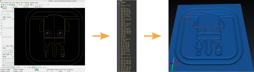
When you first get started with your CNC you will probably try cutting a few preexisting GCodes but soon you will want to make your own. The first step in that process is to create a drawing using a CAD or drawing software such as LibreCAD (2D) or Inkscape (2D). There are many guides online explaining how to install and use these programs.
Once you have a drawing saved in DXF format you will need to convert it to GCode using CAM software. You can use commercial programs such as Fusion360 or MasterCAM but there are also free and Open-Source solutions such as CAMotics, Inkscape's gcodetools plugin and pyCAM. In this guide, we will focus on using CAMotics and TPL. A quick Internet search will yield guides on using other software.
Using CAMotics and TPL
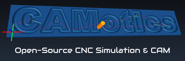
CAMotics is a free and Open-Source CNC simulation software. It supports a CNC programming system called TPL (Tool Path Language) that makes it much easier to create GCode.
If have experience with JavaScript or similar programing languages then TPL will be very easy to learn. If you have no programming experience, then you can use this guide to cut-and-paste the simple TPL program presented here and make small changes to convert your own DXF files.
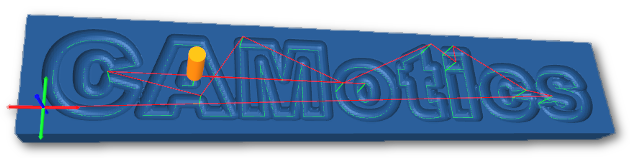
Once you've installed CAMotics, try out some of the examples by selecting them from the File menu. The "CAMotics" and "Buildbotics" examples both use DXF files and TPL. Try changing the tool or workpiece options and reruning the simulation to see how it changes.
Here we will look at the "Buildbotics" example in detail. Double click on buildbotics_logo.tpl from the left hand side of CAMotics to view the program. The complete program looks something like this:
var dxf = require('dxf');
var layers = dxf.open('buildbotics_logo.dxf');

var zSafe = 3;
var cutDepth = -1.5;

units(METRIC); // This must match the units of the DXF file
feed(1600);
speed(10000);
tool(2);

rapid({z: zSafe});

dxf.cut_layer_offset(layers.Inside,  -0.5, zSafe, cutDepth);
dxf.cut_layer_offset(layers.Tools,    0.5, zSafe, cutDepth);
dxf.cut_layer_offset(layers.Head,     0.5, zSafe, cutDepth);
dxf.cut_layer_offset(layers.Ears,    -0.5, zSafe, cutDepth);
dxf.cut_layer_offset(layers.Eyes,    -0.5, zSafe, cutDepth * 0.66);
dxf.cut_layer_offset(layers.Pupils,  -1.2, zSafe, cutDepth * 0.66);
dxf.cut_layer_offset(layers.Outline,    0, zSafe, cutDepth);

rapid({z: zSafe});
speed(0);
rapid(40, 75);
Let's break it down.
var dxf = require('dxf');
var layers = dxf.open('buildbotics_logo.dxf');
The first two lines load in the DXF library and read in the DXF file. Change the filename to read in a different file. The DXF file should be in the same directory as the TPL file. The variable layers now holds the DXF data.
var zSafe = 3;
var cutDepth = -1.5;
Next we set a couple more variables that will be used below. zSafe is the height above the workpiece where the tool can safely make rapid moves. cutDepth is how deep we will be cutting into the material.
units(METRIC); // This must match the units of the DXF file
feed(1600);
speed(10000);
tool(2);
Now we set the units mode to metric. You cauld also set it to IMPERIAL to use inches instead of millimeters. The feed rate is set to 1600 mm/min, the spindle speed to 10k RPM and tool 2 is selected. These are just examples, you must choose appropriate values for your machine, material and tool.
rapid({z: zSafe});
Move the tool up to the safe height specified above.
dxf.cut_layer_offset(layers.Inside,  -0.5, zSafe, cutDepth);
dxf.cut_layer_offset(layers.Tools,    0.5, zSafe, cutDepth);
dxf.cut_layer_offset(layers.Head,     0.5, zSafe, cutDepth);
dxf.cut_layer_offset(layers.Ears,    -0.5, zSafe, cutDepth);
dxf.cut_layer_offset(layers.Eyes,    -0.5, zSafe, cutDepth * 0.66);
dxf.cut_layer_offset(layers.Pupils,  -1.2, zSafe, cutDepth * 0.66);
dxf.cut_layer_offset(layers.Outline,    0, zSafe, cutDepth);
Here we cut each of the DXF layers using dxf.cut_layer_offset(). The three paramters passed to dxf.cut_layer_offset() are layer, offset, z-safe and cut depth.
The layer is the DXF layer. DXF layers can be selected by name or by number. DXF layers are named in the CAD software. Your DXF may only have one layer. In that case, it is easer to cut the single layer like this:
dxf.cut_layer_offset(layers[0], 0, zSafe, cutDepth);
The offset offsets the tool position from the DXF path. A positive offset will cut outside of the path. For example, you might want to offset by half the tool diameter. A negative value will cut inside the path and zero will cut exactly on the path.
rapid({z: zSafe});
speed(0);
rapid(40, 75);
Finally, we move back up to the safe height, turn off the spindle and move to a position out of the way.