This manual describes Buildbotics Controllers with V2 software. V2 software only runs on Buildbotics Controllers that are equipped with a Raspberry Pi 4 and a Version 17 main board.
Follow these links to access previous versions of the manual:
- Buildbotics Controller Manual for V1.2 to V1.0.4 software
- Buildbotics Controllers Manual for V1.0 software
- Buildbotics Controller Manual for V0.4 software
Overview
Buildbotics is committed to providing a CNC tool chain that is easy to use, affordable, and completely Open-Source. Key to this commitment is the Buildbotics CNC Controller.
The Buildbotics 4-Axis CNC Controller hardware and software are completely Open-Source. All basic features needed for machine homing and loading and executing GCode files are included.
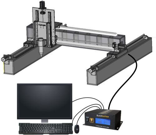
The Buildbotics CNC Controller does not require a dedicated computer to run. It is a stand-alone device that acts as a web server. Users can configure and control it from a web browser that connects through an Ethernet port or across a WiFi connection. Alternatively, you can connect a monitor, a USB keyboard, and a USB mouse directly to the controller to run your CNC machine with no computer at all!
Another unique feature is the gamepad used for local control. Just plug it into one of the USB ports and start jogging the machine on any axis.
Plug a webcam into a USB port and the Buildbotics Controller becomes a video server. You can now keep an eye on cutting operations while you watch the game in another room.
Limit switches, Z-axis probing, PWM spindle control, RS485 spindle control, 0 - 10 Volt analog spindle control, and e-stop interfaces are all made available through a DB25 connector on the back. A DB25 breakout board provides easy access to these features.
Motor drivers for each of the four axes are built into (and powered by) the controller. This simplifies the overall design, configuration, and implementation of your CNC build.
The Buildbotics CNC Controller provides the ability to bypass the internal motor drivers and exposes the control signals through a DB15 connector on the back panel. As good as the internal drivers are, some users have needs that go beyond the capabilities of the internal drivers.
Pre-made cables are provided for connecting to the motors and power supply. These cables really save time when connecting to a new machine. To make life even easier, the power connector is compatible with some standard power adapters.
Heat dissipation was carefully considered throughout the design. As a result, the controller electronics are inside a sleek enclosure with no fan. Cuttings won't get sucked into the controller even when operating right next to the CNC machine. Exposed electronics are a thing of the past.
The controller is integrated with CAMotics; a popular Open-Source CAM and CNC Simulator. CAMotics allows importing GCode, DXF, or STL files. Alternatively, CAMotics allows writing cutting programs in Javascript. After simulating, CAMotics converts the output to GCode and can connect directly to the Buildbotics Controller and provide a real-time simulation as the machine is cutting.
Performance is critical for CNC Controllers. The Buildbotics CNC Controller is a powerhouse working on 24 to 48 Volts DC, supplying up to 6 amps on each motor, and generating over 250,000 steps per second on each axis. S-curve acceleration and deceleration eliminate machine movements caused by sudden starts and stops. These capabilities provide smooth and fast operation on nearly any machine running NEMA 17 or 23 stepper motors and many machines running NEMA 34 stepper motors. Even larger motors can be controlled using external drivers.
Controller Operation
Safety
Machine tools are inherently dangerous. Users must be trained on all hazards associated with the machine before use. Examples of hazards commonly associated with machine tools include:
- Electrical energy
- Loud noise
- Dust (often toxic)
- Toxic gases
- Flying material and parts
- Pinch points
- Sharp edges
- Sharp points
- Rotating machinery
- Rapidly moving parts
- Fire
- Heat
These hazards are complicated, and often exacerbated by allowing computers to control them. The Buildbotics CNC Controller is a computer that controls machine tools. Users must be on constant guard against the possibility that the controller will cause the machine to do something that is unexpected. Users are responsible for mitigating these hazards before using the Buildbotics CNC Controller.
Please also read our General Disclaimer as it applies to the information contained in this manual and on our website as well as to our products.
Users that find these restrictions and limitations unacceptable should contact the Buildbotics LLC customer service department (707) 559-8539 for a refund prior to using or energizing the product.
Turning on the controller
Turn off the “Enable” switch, connect power and then turn on the “Enable” switch. After enabling the controller, the LCD screen will immediately light up, then the controller will fully boot in about a minute.
LCD Display
The LCD display is located on the front panel of the Buildbotics Controller and presents status information. The LCD display will immediately illuminate after power is connected and the Enable switch is switched to “Enable”. Then, the controller fully boots in about a minute. Once this display is presented, the Buildbotics Controller is ready for operation.
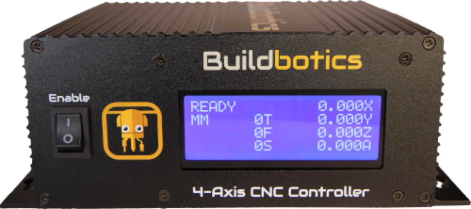
Ready Screen
The ‘state’ field reflects the state of the CNC controller. The possible values in the state field are:
- READY
- JOGGING
- ESTOPPED
- RUNNING
- STOPPING
- HOLDING
The ‘units’ field is located immediately below the ‘state’ field and indicates whether the controller is operating in Metric or Imperial units. “MM” indicates Metric and “INCH” indicates Imperial units.
The ‘T’ field indicates which tool is currently loaded. For instance, 0T means tool ‘0’ is loaded and 2T means tool ‘2’ is loaded.
The ‘F’ field indicates the current feed rate. For instance, if the controller is operating in Imperial units and the feed rate is 60 inches per minute, the “F” field will show 60F
The ‘S’ field indicates the spindle speed setting in revolutions per minute (RPM). It does not reflect the actual speed that the spindle is turning. For instance, if the spindle speed is set to 9000 RPM, the ‘S’ field will show 9000S.
The axis position fields on the right show the current position of the respective axis in millimeters or inches depending on whether the controller is operating in Metric or Imperial units.
If a gamepad is plugged in, you can scroll through two additional screens by pressing on the left or right side of the menu navigation button on the gamepad.
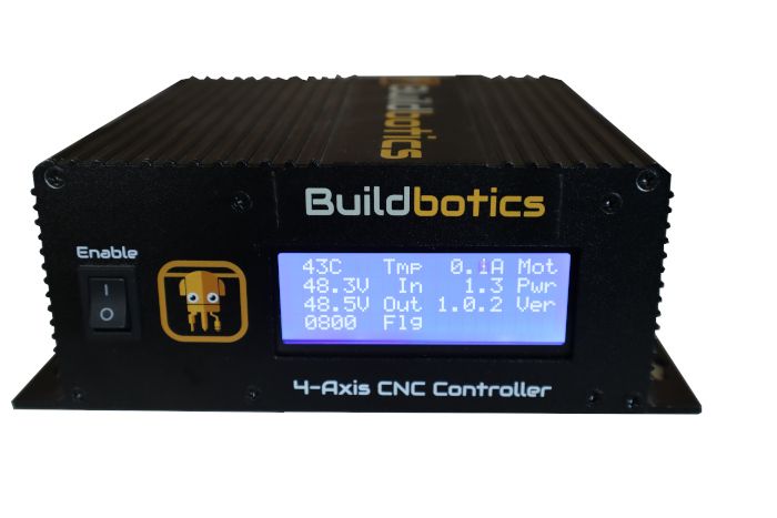
Status Screen
One push to the left brings up a status screen.
The status screen displays the temperature inside the enclosure 'Tmp', the total motor current 'Mot', the power consumed in watts 'Pwr', the input voltage from the power supply 'In', the voltage being sent to the motor drivers 'Out', the current version of the controller software 'Ver' and the status flags (Flg). The status flags are for internal use by Buildbotics.
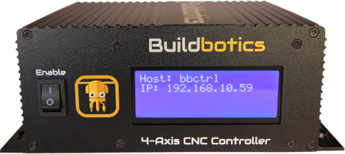
Network Screen
Pushing the menu navigation button again brings up the Network screen, which displays the host name of the Buildbotics Controller. If the controller is connected to a local area network, the IP address is displayed as well.
Backpanel Connections
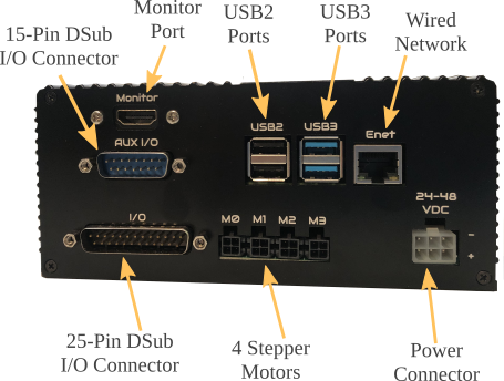
The backpanel connections on the Buildbotics Controller include:
- One Monitor port (labeled Monitor)
- One 100 Mbps Ethernet jack (labeled ENet)
- 2 USB2 ports (labeled USB2)
- 2 USB3 ports (labeled USB3)
- 4 motor ports (labeled M0, M1, M2, and M3)
- A DC input power connector (labeled 24-48 VDC)
- A 25-Pin male DB25 connector (labeled I/O)
- A 15-Pin male DB15 connector (labeled Aux I/O)
Power Supply
The Buildbotics Controller runs from a single power supply with voltage between 24 and 48 Volts DC and can sink up to 15 amps of DC current.
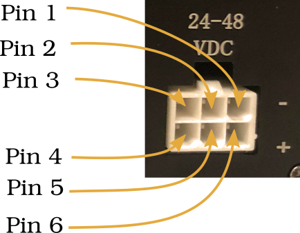
The power connector has 6 pins. Pins 1, 2, and 3 are on the top row and are connected to ground. Pins 4, 5, and 6 are on the bottom row and are connected to dc voltage between 24 and 48 volts.
The connector has reverse polarity protection built in. However, connecting power and ground to the top row or to the bottom row simultaneously will provide a short circuit and a potentially violent failure. The Buildbotics Controller comes with a pre-made power supply cable that plugs into the “24-48 VDC" connector and can be wired directly to a DC power supply.
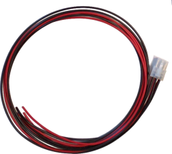
The “24-48 VDC” connector mates with a Molex 39-01-2060 plug that is equipped with Molex 39-00-0038 female pins. Attaching wires to the 36-00-0038 female pins and inserting the pins into the 39-01-2060 housing requires some practice. If you choose to build your own cable, make sure that the wire and pins used are big enough to handle the current requirements for your application. A premade power cable is shipped with the Buildbotics Controller.
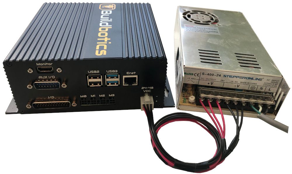
The following picture shows a typical power supply connected to the power supply connector using the Buildbotics supplied pre-made power cable. Notice that the three bottom pins on the power supply connector are attached to the +V terminals and the three top pins on the power supply connector are attached to -V terminals on the DC power supply.
USB Devices
Several types of peripheral devices connect to the Buildbotics Controller through USB ports. They may include:
- The Gamepad controller
- USB thumb drive
- Keyboard
- Mouse
- Web camera
- USB Wifi Antenna
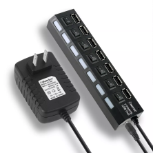
- Powered USB hub
There are two USB2 ports and two USB3 ports available on the back of the Buildbotics Controller. The USB3 ports are faster. USB3 devices may not be compatible with the USB2 ports.
The amount of power available to the USB ports is limited. If more than four ports are required or if the Buildbotics Controller cannot power all of the USB devices it serves, a powered USB hub is recommended.
Monitor, Keyboard & Mouse
Use the following steps to operate the Buildbotics Controller without a computer:
- Connect a monitor to the "Monitor" port on the back of the controller.
- Plug a USB mouse into one of the USB ports on the back of the controller.
- Plug a USB keyboard into another USB port on the back of the controller.
- Attach power to the monitor and turn it on.
- Configure the monitor input source.
- Turn on the controller.
Alternatively, users can use a touch screen monitor to eliminate the keyboard and mouse. Buildbotics recommends the ASUS VT168H touch screen monitor.
The Buildbotics Controller is pre-configured with a software keyboard. The software keyboard appears when a text field is selected using a local monitor unless the automatic keyboard is disabled. The software keyboard can be toggled on and off using the keyboard icon at the top of the screen.
The software keyboard is not provided on networked connections. Users that want to use a software keyboard on networked connections can install one on their local computer or local browser.
The Buildbotics logo is displayed on the local monitor while the controller is booting. When the controller has completed its boot process, the “CONTROL” page is displayed.
Network
The Buildbotics Controller offers wired and wireless network connections. Wireless connections can be configured from the Network tab on the SETTINGS Page.
While Internet access is not required to operate the Buildbotics Controller, it is desired. Internet access provides direct access to this manual, and makes software upgrades very easy.
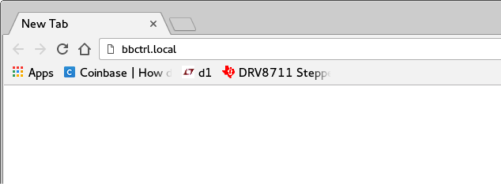
After the Buildbotics Controller is attached to a local area network, it can be accessed across the network by entering the hostname concatenated with .local (“hostname.local”) or the IP address of the Buildbotics Controller into the address bar on any standard browser.
The default hostname is “bbctrl”. So, new controllers can be accessed by putting “bbctrl.local” in the address bar of the browser. Some computers may not support the hostname.local address and require that the IP address be entered into the address bar.
The IP address can be acquired by scrolling to the “Network” LCD screen on the controller using the gamepad.
Accessing the Buildbotics Controller from outside the local subnet is not supported.
Ethernet
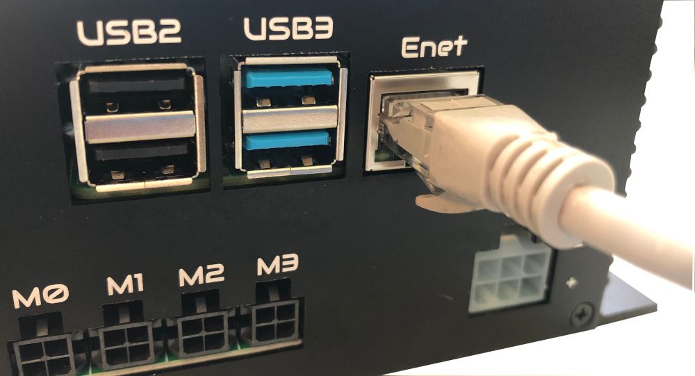
The Buildbotics Controller connects to standard Ethernet networks via the Ethernet RJ-45 port on the back panel. To attach the Buildbotics Controller to the local network, simply plug a standard CAT 5 or CAT 6 Ethernet cable into the jack labeled “Enet” on the back of the controller and plug the other end into a network port on an Ethernet network router or switch.
Wireless
The Buildbotics CNC Controller has a built-in wireless adapter.
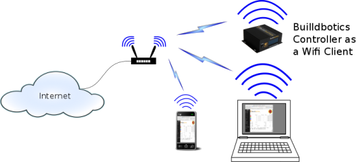
Since the Wifi antenna for the Buildbotics Controller is inside the metal enclosure, the Wifi signal strength is significantly reduced. This may result in poor or no communications. To boost the signal strength, Buildbotics recommends a Wifi antenna. Not all USB Wifi antennas are compatible with the Buildbotics Controller. Antennas that utilize the MT7601u or the RT5370 chip set have been found to work correctly.
To install the antenna, simply plug it into an empty USB port on the Buildbotics Controller and configure the Builbotics Controller as described in the Network tab on the SETTINGS Page.
Gamepad
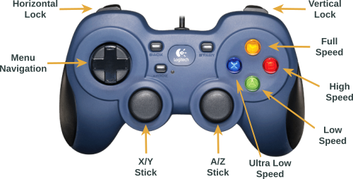
The Buildbotics Controller comes with a wired USB gamepad controller that can be used to control movement on the X, Y, Z, and A axes and to scroll through the LCD screens on the controller. The gamepad attaches to the Buildbotics CNC Controller via any of the four USB ports on the back panel. Once attached, the gamepad can be used to move the CNC head in any direction at various speeds.
The following table describes the actions that can be achieved using the gamepad.
| Movement | Buttons | Comments |
|---|---|---|
| Simultaneous X and Y movement |
X/Y stick | Causes the CNC head to move in the direction that the X/Y stick is moved. |
| X movement only | X/Y stick and Horizontal Lock simultaneously |
Restricts movement to X-axis only |
| Y movement only | X/Y stick and Vertical Lock simultaneously |
Restricts movement to Y-axis only |
| Simultaneous A and Z movement |
Z/A stick | Causes up and down and rotational movement. |
| Z movement only | Z/A stick and Vertical Lock simultaneously |
Causes up and down movement only. |
| A movement only | Z/A stick and Horizontal Lock simultaneously |
Causes rotational movement only. |
| Very slow speed | Speed 1 | Set movement speed to 1/128th of full speed. |
| Slow speed | Speed 2 | Set movement speed to 1/32nd of full speed. |
| Medium speed | Speed 3 | Set movement speed to 1/4th of full speed. |
| Full speed | Speed 4 | Set movement speed to full speed. |
| Scroll to next LCD display |
Press right side of Menu Navigation button |
Moves to the next LCD display (Ready Display-> Network Display-> Status Display-> Ready Display) |
| Scroll to previous LCD display |
Press left side of Menu Navigation button |
Moves to the previous LCD display (Ready Display-> Status Display-> Network Display-> Ready Display) |
Other gamepads may work perfectly, work but have the buttons in different places, partially work, or not work at all.
25-pin I/O Port
The Buildbotics Controller is equipped with a male DB25 connector for access to a number of I/O ports. The DB25 I/O Port is found on the back panel of the Buildbotics Controller.
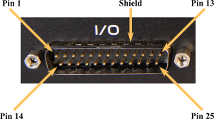
The following table describes each pin on the DB25 I/O port.
| Pin | Type | Possible Values (see note) |
Default assignment | |
|---|---|---|---|---|
| 1 | mappable digital output |
VOL, VOH | flood control | |
| 2 | mappable digital output |
VOL, VOH | mist control | |
| 3 | mappable digital input |
VIL, VIH | Motor 0 minimum limit switch |
|
| 4 | mappable digital input |
VIL, VIH | Motor 0 maximum limit switch |
|
| 5 | mappable digital input |
VIL, VIH | Motor 1 minimum limit switch |
|
| 6 | SPIN_0-10 | 0-10VDC | User controlled 0 to 10 Volt analog output |
|
| 7 | Gnd | |||
| 8 | mappable digital input |
VIL, VIH | Motor 1 maximum limit switch |
|
| 9 | mappable digital input |
VIL, VIH | Motor 2 minimum limit switch |
|
| 10 | mappable digital input |
VIL, VIH | Motor 2 maximum limit switch |
|
| 11 | mappable digital input |
VIL, VIH | Motor 3 minimum limit switch |
|
| 12 | mappable digital input |
VIL, VIH | Motor 3 maximum limit switch |
|
| 13 | RS485 A | Spindle control (negative side of RS485 differential pair) |
||
| 14 | RS485 B | Spindle control (positive side of RS485 differential pair) |
||
| 15 | mappable digital output |
VOL, VOH | tool enable | |
| 16 | mappable digital output |
VOL, VOH | tool direction | |
| 17 | Tool PWM | VOL, VOH | Spindle speed control (pulse width modulated signal alternating between VOL and VOH) |
|
| 18 | mappable analog input |
0-3.3Volts | ||
| 19 | Gnd | 0V | Ground | |
| 20 | +5V | 5V | 5 Volts | |
| 21 | mappable digital output |
VOL, VOH | fault indicator | |
| 22 | mappable digital input |
VIL, VIH | probe input | |
| 23 | mappable digital input |
VIL, VIH | estop input | |
| 24 | mappable analog input |
0-3.3Volts | ||
| 25 | Gnd | 0V | Ground | |
| 26 | Gnd | 0V | Ground (shield) |
| Logic Name | Minimum | Maximum | Definition |
|---|---|---|---|
| VOL | 0 | 0.5 VDC | Logic output low |
| VOH | 4.5VDC | 5.3VDC | Logic output high |
| VIL | 0 | 0.3VDC | Logic input low |
| VIH | 1.5 VDC | Open or up to 50VDC |
Logic Input High Up to 50 Volts can applied with out damaging the input |
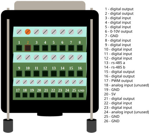
Typically, a female DB25 breakout board is used to interface with the DB25 I/O Port. The following image shows a DB25 breakout box that is used for interfacing with the Buildbotics Controller. A DB25 breakout box is supplied with the Buildbotics CNC Controller.
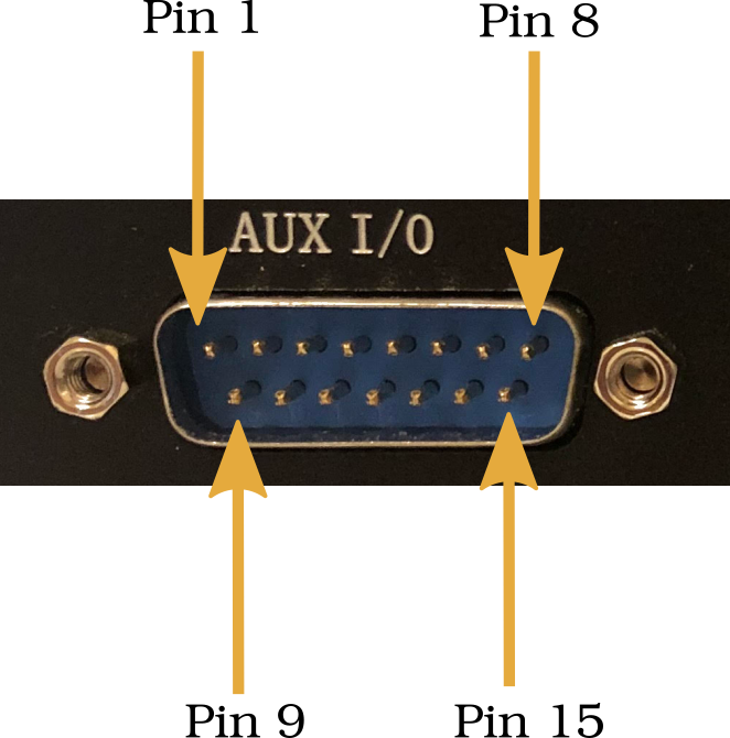
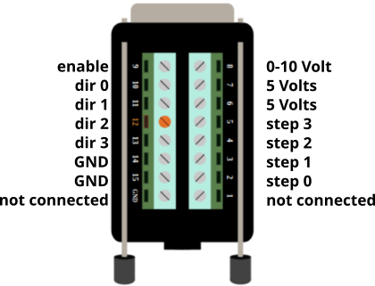
15-Pin Auxilliary I/O Port
The Buildbotics Controller is equipped with a male DB15 Auxilliary I/O connector on the back panel.
The 15-Pin Auxilliary I/O connector provides access to the motor enable, step, and direction inputs to the motor drivers. These lines provide the ability to bypass the internal motor drivers and control external drivers.
In addition, the +5V, 0-10 volt analog output and Gnd outputs are duplicated from the 25 Pin I/O port.
| Pin | Name | I/O | Possible values | Description |
|---|---|---|---|---|
| 1 | not connected | |||
| 2 | Step_0 | O | VOL, VOH | Low to high transition for each step (see note) |
| 3 | Step_1 | O | VOL, VOH | Low to high transition for each step (see note) |
| 4 | Step_2 | O | VOL, VOH | Low to high transition for each step (see note) |
| 5 | Step_3 | O | VOL, VOH | Low to high transition for each step (see note) |
| 6 | 5V | 5 Volts | 5 Volt source | |
| 7 | 5V | 5 Volts | 5 Volt source | |
| 8 | 0-10VDC | O | 0 to 10 Volts | User controlled 0 to 10 volt output |
| 9 | Motor_Enable | O | VOL, VOH | VOH enables motor drivers |
| 10 | Dir_0 | O | VOL, VOH | VOH for forward direction | 11 | Dir_1 | O | VOL, VOH | VOH for forward direction |
| 12 | Dir_2 | O | VOL, VOH | VOH for forward direction |
| 13 | Dir_3 | O | VOL, VOH | VOH for forward direction |
| 14 | Gnd | Ground | ||
| 15 | Gnd | Ground | ||
| 16 | not connected |
| Logic Name | Minimum | Maximum | Definition |
|---|---|---|---|
| VOL | 0 | 0.5 VDC | Logic output low |
| VOH | 4.5VDC | 5.3VDC | Logic output high |
Motors
The Buildbotics Controller has four motor outputs, labeled M0, M1, M2, and M3. Each motor output can drive a separate axis, or two motor outputs can be assigned to the same axis. One or more motors can be connected to a single motor output. If more than one motor is connected to a single motor output, they can be wired in series or parallel.
The motor driver outputs can supply up to 6 amps peak current to each coil. Each motor has two coils. If identical motors are connected to a single motor output and they are wired in parallel, then those motors will share the current equally. The current through each motor coil is an approximated sine wave and there is a 90° phase shift between the two coil drivers on each motor output. Since the currents are out of phase, the peak total instantaneous current to a single motor output can be as high as 8.48 amps.
The total average motor current is limited to 15 amps. But, the sum of the peak motor currents can far exceed 15 amps.
Exceeding 15 amps of average current will cause the controller to shut down with a “Motor overload” fault. The average current drawn depends heavily on the load placed on the motors.
Users should refer to the data sheet for the motors being used and configure the motors for the current rating shown in the data sheet. See, the Motor tab section on the SETTINGS Page for more information on this subject.
The voltage output to each motor driver is a pulse width modulated (PWM) voltage with an amplitude equal to the input DC voltage being supplied to the Buildbotics Controller from the power supply.
The motor output connectors are shown below. All four motor output connectors are wired the same. The motor output connectors mate with Amphenol 10127716-04LF connectors equipped with Amphenol 10127718-001LF female crimp pins.
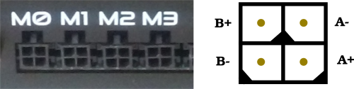
When connecting motors:
- Connect the B+ pin (upper left) to the positive side of the B coil on the motor.
- Connect the B- pin (lower left) to the negative side of the B coil on the motor.
- Connect the A+ pin (lower right) to the positive side of the A coil on the motor.
- Connect the A- pin (upper right) to the negative side of the A coil on the motor.
These connections will cause your motor shafts to turn either clockwise or counterclockwise. If the motors are turning in the wrong direction, simply reverse either the A+/A- pair or the B+/B- pair. Do not reverse both pairs.
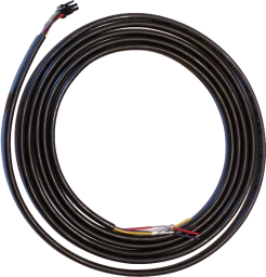
It takes some practice to properly attach the Amphenol 10127716-04LF connectors equipped with Amphenol 10127718-001LF female crimp pins to a cable. In order to avoid this difficulty, the Buildbotics Controller comes with four, 10-foot motor cables. Buildbotics motor cables are wired as shown in the following table.
| Conductor | Premade cable wire color |
|---|---|
| A+ | Red |
| A- | Black |
| B+ | Yellow |
| B- | White or Purple |
Some CNC machines use two motors to drive a single axis. If an unused motor output is available on the Buildbotics Controller, simply assign the second motor output to the same axis and connect the second axis motor to the second output.
A single output port can drive two motors with certain limitations. It is recommended that the motors be wired in parallel when driving two motors from a single motor output. The limitations are:
- Since the two motors are wired in parallel, the current supplied by the motor output will be doubled. For instance, if each motor has a current rating of 2.8 amps, then the current on the motor output must be set to 5.6 amps. The maximum output current from a motor port on the Buldbotics Controller is 6 amps, so you cannot connect two motors that require more than 3 amps each to a single port.
- When motors are wired in parallel on a single output port, they tend to resonate with one another. When the resonance occurs, the motors will stall. As a result, the motors must run at a speed below this resonance to avoid stalls. Unfortunately, it is not possible to predict the speed at which this resonance will occur without wiring them up and connecting them to the machine.
In many cases, the two motors will face one-another and must turn in opposite directions.
If the motors must turn in opposite directions, then one of the motors will have either the A+/A- pair reversed or the B+/B- pair reversed (but not both). The following image shows the B+/B- pair reversed on the motor on the right which causes the motors to turn in opposite directions.

Refer to the Motors tab on the SETTINGS Page for information on configuring motors.
Spindle
The Buildbotics Controller can control a spindle through a Pulse Width Modulated (PWM) interface, a 0 to 10 volt analog interface, or an RS-485 interface.
RS-485
Use the following procedure to connect a spindle controller (1) to the Buildbotics Controller using the RS-485 interface:
- Disconnect power from the spindle (2).
- Cut a pair of wires to a length that will reach from the Buildbotics Controller to the spindle controller (1).
- Twist the two wires at about 1 turn per inch to reduce noise and interference.
- Connect the pair to the positive and negative RS-485 terminals on the spindle controller (1)
- Connect the plus side of the RS-485 pair to pin 14 on the DB25 breakout board.
- Connect the minus side of the RS-485 pair to pin 13 on the DB25 breakout board.
- Connect the DB25 breakout board to the back of the Buildbotics Controller.
- Reconnect power.
Refer to the Tool tab on the SETTINGS Page for instructions on how to configure the Buildbotics Controller to use the RS-485 interface. Refer to the spindle controller manual for instructions on how to configure the spindle controller (1).
If the connection does not come up, or if errors occur, try reversing the RS-485 pair.
PWM
Use the following procedure to connect to a PWM spindle controller (1):
- Disconnect power from the spindle (2) and the Buildbotics Controller.
- Refer to the DB25 Connector Pin Description Table to confirm that the Buildbotics output signals are compatible with the inputs on the PWM spindle controller. If not, level shifters may be required.
- Connect the 'Tool Enable' pin (default for pin 15) on the DB25 breakout board to the 'Enable' pin on the spindle controller (1).
- Connect the 'Tool Direction' pin (default for pin 16) on the DB25 breakout board to the 'Direction' pin on the spindle controller (1).
- Connect the 'Spin PWM' pin (17) on the DB25 breakout board to the PWM terminal on the spindle controller (1).
- Connect one of the Gnd pins (7, 19, or 25) to the analog signal ground terminal on the spindle controller (1).
- Reconnect power.
Refer to the Tool tab on the SETTINGS Page for instructions on how to configure the Buildbotics Controller to control the PWM spindle controller.
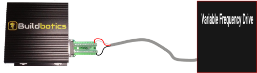
0 to 10 Volt Analog
Use the following procedure to connect to the 0 - 10 volt analog interface on the spindle contoller (1):
- Disconnect power from the spindle (2) and the Buildbotics Controller.
- Refer to the DB25 Connector Pin Description Table to confirm that the Buildbotics output signals are compatible with the inputs on the spindle controller (1). If not, level shifters may be required.
- Connect the 'Tool Enable' pin (default for pin 15) on the DB25 breakout board to the 'Enable' pin on the spindle controller (1).
- Connect the 'Tool Direction' pin (default for pin 16) on the DB25 breakout board to the 'Direction' pin on the spindle controller (1).
- Connect the 'SPIN_0-10' pin (6) on the DB25 breakout board to the 0-10 Volt Analog input on the spindle controller(1).
- Connect one of the Gnd pins (7, 19, or 25) to the analog signal ground terminal on the spindle controller(1).
- Reconnect power.
Refer to the Tool tab on the SETTINGS Page for instructions on how to configure the Buildbotics Controller to control the Analog 0 to 10 Volt interface. Refer to the spindle controller manual for configuration information on spindle controller (1).
Note 1 - Spindles can be controlled directly, through a Variable Frequency Drive (VFD), or through a spindle controller. The term 'spindle controller' is meant to include all three cases.
Note 2 - Make sure to disconnect power from the spindle controller or Variable Frequency Drive.
Power Budget
The power budget is limited by the Buildbotics Controller and by the capability of the external power supply. The Buildbotics Controller can draw up to 15 amps of current from the power supply. Refer to the power supply specification to determine its maximum current rating.
When choosing motors, it is important to estimate the maximum total current that will be consumed at any given time.
Estimating stepper motor current can be confusing because the specifications often provide a current rating, and it can be tempting to just add up the current rating of each motor to get the total current drawn from the motors. This approach will result in overestimating the current requirements for the following reasons:
- The current rating provided for stepper motors is the per-phase peak current. So, the peak current is actually specified for each phase. The current between the two phases is 90 degrees out of phase so they add and subtract throughout each cycle. The actual sum of the peak currents for a motor can be 1.41 times the per-phase current rating.
- The Buildbotics Controller ensures that the proper amount of current is supplied to the motor coils as needed. However, for a good portion of the time, the current is supplied from internal capacitors and from energy storage within motor coils. Therefore, the amount of time when current is being drawn from the power supply is small, resulting in lower average current.
A rule-of-thumb approach is to estimate that the actual average current drawn by a motor from the power supply will be one third of the rated motor current. For instance, if the motor current rating is 4 amps, then a reasonable estimate of current drawn from the power supply would be 4 * (⅓) = 1.3 amps, and a reasonable estimate of current for three 4 Amp motors would be 1.3 * 3 = 3.9 amps.
If the total average motor current exceeds 15 amps, the Buildbotics Controller may shutdown during operation to avoid overheating and damage to the controller. Here are a few ways to avoid these shutdowns:
- The Buildbotics Controller can operate anywhere between 24 and 48 volts. Operating at higher voltages will cause less current to be drawn at a specific torque and speed. The danger here is that the higher voltage will also produce higher speeds and most people will be tempted to operate at the highest speed possible. The higher speed will result in drawing more current.
- Many bipolar stepper motors can be wired in series or parallel. Motors wired in parallel will generally run faster but they draw more current. However, wiring these motors in series cuts the current in half.
- Sometimes machines are built with identical motors on all axes, even though the speed and torque requirements are not the same for all axes. If this is the case, consider changing the motors on any axis that is not required to turn as fast or produce as much torque.
- When operating your machine, simply limit the speed to a value that avoids the highest current drawn.
Web Camera
Simply plug a motion JPEG (MJPEG) compatible webcam into one of the unused USB ports on the back of the controller and the web camera display will automatically become visible on the user interface.

Not all web cameras will work correctly. Buildbotics has tested the one shown.
User Interface
The Buildbotics Controller can be accessed, configured, and controlled from a local monitor, USB mouse, and USB keyboard or across a local network from a computer or device with a standard browser. The Monitor, Keyboard, and Mouse Section and the Network Section describe how to access the Buildbotics Controller user interface.
The interface is nearly the same in both cases and is described for both configurations in this section.
Common Features and Controls
The user interface for the Buildbotics Controller consists of several pages. All of these pages have a few things in common.
Tool Tips
Many of the controls on these pages have 'tool tips' that provide hints about what the control does. Hovering over the control with your mouse causes the 'tool tip' to appear.
Navigation Bar
The user interface is presented on several pages. These pages are the:
- CONTROL Page
- 3D VIEW Page
- EDITOR Page
- CAMERA Page
- FILES Page
- SETTINGS Page
- DOCS Page
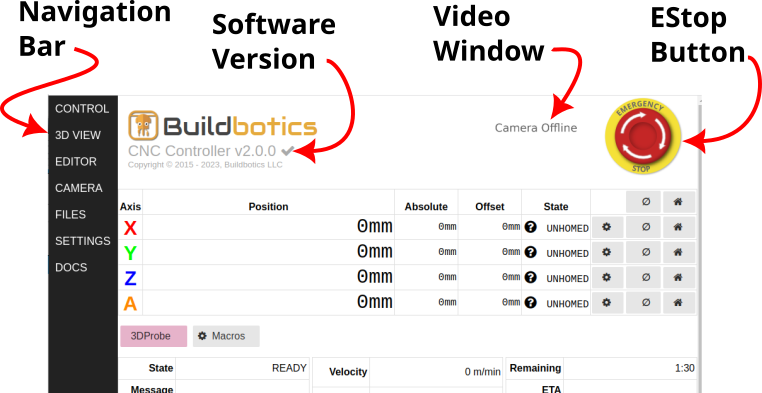
A dark gray 'navigation bar' is displayed on the left side of each page and provides links to each of the other pages. On small screens, this bar becomes a pull-down menu. Resizing the window to be narrow will also cause the bar to become a pull-down menu.
Emergency Stop Button
A yellow and red "emergency stop" button is present in the upper right part of the screen on all pages. Clicking this button puts the controller in the 'ESTOPPED' state. When 'ESTOPPED', all motors and the spindle are disabled, all position and homing information is lost, and the yellow ring blinks between orange and yellow.
Clicking the emergency stop button while the Buildbotics Controller is in the 'ESTOPPED' state attempts to clear the "emergency stop". If the "emergency stop" clears, the outer ring changes back to solid yellow. The "emergency stop" may not clear if the hardware "emergency stop" switch or if a limit switch is active.
The National Fire Protection Agency (NFPA 79) requires that the class of emergency stop button be determined through a risk assessment. The soft "emergency stop" button on these web pages and the estop pin (pin 23 on the DB25 I/O connector by default) are both software controlled, and cannot be used for safety. If your risk assessment requires an emergency stop button to be installed for safety purposes or mission critical applications, then Buildbotics LLC recommends installing a “listed“ hardware Emergency Stop button in line with system power.
Software Version
The current software version is displayed just below the Buildbotics logo. A check mark is displayed next to the version number if the latest version is currently loaded. If a new version is available, a recommendation to upgrade to the latest version is displayed. The check mark and recommendation are not displayed if internet access is not available.
Automatic checking for new software versions can be disabled from the Admin tab on the SETTINGS page.
Video
If a web camera is connected, a small video window is displayed just left of the emergency stop button on all pages except the CAMERA page. If no camera is connected, "Camera Offline" is displayed in the window.
Clicking on the window navigates away from the current page and to the CAMERA Page.
Virtual Keyboard
The local monitor interface provides a virtual keyboard. This allows users to eliminate the hardware keyboard. The virtual keyboard can be toggled on and off by clicking the Virtual Monitor Keyboard button at the top of the screen.
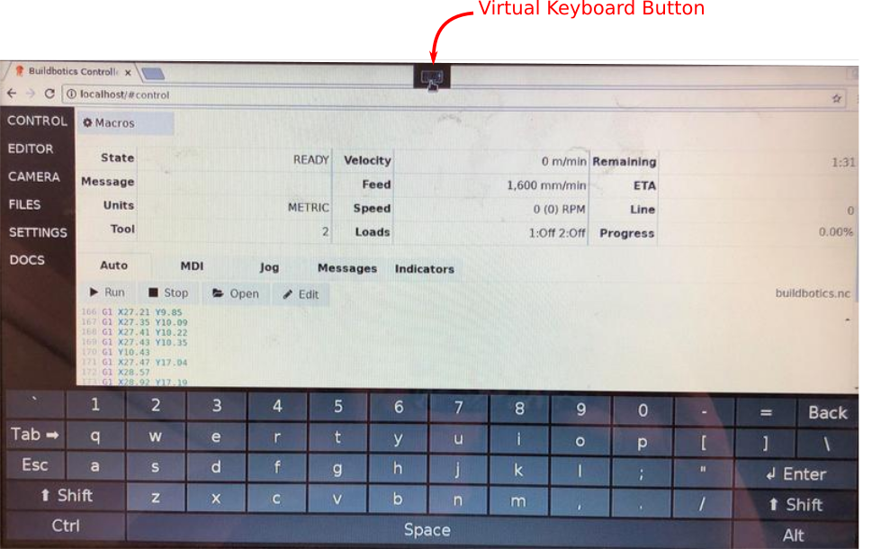
The virtual keyboard is not provided when accessing the controller from across a local area network.
By default, on the local monitor, the virtual keyboard will appear every time you select a text input field on the user interface. This behavior can be disabled on the Admin tab on the SETTINGS page.
CONTROL Page
The Control page provides real time status and feedback information about the attached machine, and allows controlling the machine through manual jogging, running GCode commands, running macros, or running GCode programs.
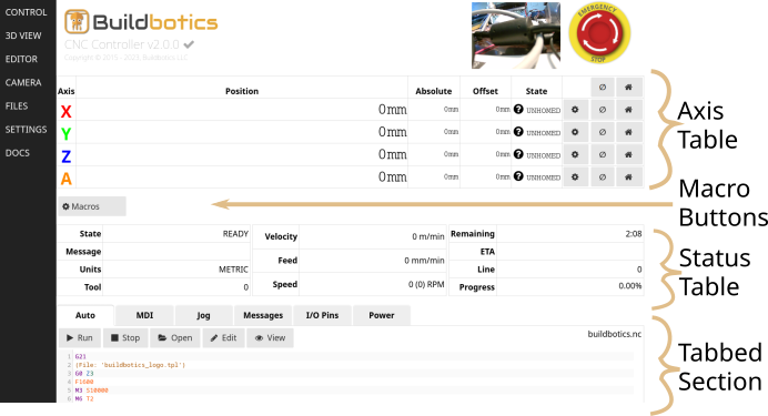
The CONTROL Page consists of the Axis Table, the Macro Buttons Section, the Status Table, and the Tabbed Section.
Axis Table
The Axis table is at the top of the CONTROL page and gives the following information for each active axis:
- Position - This is the logical position. GCode commands and programs will move relative to this position. For instance, the command “G0 X10” will cause the X axis to move to 10mm and 10mm will reflect in this field. This assumes that metric units and absolute position mode are being used. This value will also show on the LCD 'Ready' screen.
- Absolute - This is the actual position of the machine relative to its homed value.
- Offset - Offset is equal to Position - Absolute. This is useful when you want your program to run from some position other than home. For instance, the physical home value may be at the lowest position along an axis, but the program causes the axis to move to negative values. The offset can shift the zero position to another point along the axis.
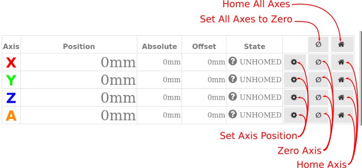
The buttons on the right side of the Axis table are used to home the axes, set the position of the axes, and zero the position of the axes.
The top 'Home' button causes all axes to initiate their homing sequences. The other 'Home' buttons initiate the homing sequence (1) for their respective axes.
The top 'Zero Axis' button sets the current position of all axes to zero. If the axis has been homed, this button sets the 'Offset' field to be equal zero minus the value in the Absolute field.
The 'Set Axis Position' buttons allow the user to set the 'Position' field to a desired value. If the axis has been 'homed', the 'Offset' field will be adjusted to equal the new value in the 'Position' field minus the value in the 'Absolute' field. If the axis has not been homed, the value in the 'Absolute' field is set to the new value in the 'Position' field and the value in the 'Offset' field is set to zero.
The 'State' fields reflect the 'Homing' state of the respective axis. Possible values and their meanings are:
- UNHOMED - The axis has not been homed. The background color for the Axis, Position, Absolute, Offset, and State fields will be white.
- HOMED - The axis has been homed. In this case, the background color of the Axis, Position, Absolute, Offset, and State fields will be green.
- NOFIT - The machine has been homed, but the G-Code program that is currently loaded will not fit within soft limits (2) of the machine.
If an axis is homed and a command is issued that would cause the machine to travel beyond a soft limit for that axis, the program will stop and an error message will be presented.
Note 1 - Homing sequences are described in the 'Homing' section of the 'Motors' Tab on the 'SETTINGS' Page.
*Note 2 - Soft limits are defined on the Motors tab on the Settings page.
Macro Buttons
The Macro Buttons section of the 'CONTROL' Page provides a button for each Macro button that has been assigned. Each button is labeled with the name and color that is assigned to the button. Simply click one of these buttons to run the program that has been assigned to that button.
The last button is gray in color, has a gear icon, and is labeled 'Macros'. Clicking this button navigates to the 'Macros' tab on the 'SETTINGS' Page to view, add, or remove macro buttons.
Status Table
The status table provides real-time information about the state of the machine and programs.
The "State" field reflects the state of the CNC Controller and the current action being taken. The possible values in the state field are:
- READY - The controller is ready to execute commands.
- HOMING - A homing sequence is underway.(1)
- JOGGING - The user is currently moving an axis with the gamepad or via the Jog tab on the CONTROL Page.
- ESTOPPED - The controller is estopped. This means that the estop hardware switch has been activated, the soft estop button has been clicked, or a limit switch has activated unexpectedly.
- RUNNING - A command or program is currently being executed.
- STOPPING - The current command or program is stopping; probably because the user clicked the stop button.
- HOLDING - The current command or program is paused; probably because the user clicked the pause button or the controller is waiting for the user to respond to a dialog.
The 'Message' field is often blank, but may report a message to describe the machine state. More details can be found by selecting the 'Messages' Tab.
The 'Units' field specifies whether GCode commands will be interpreted in metric or imperial units. The 'Position', 'Absolute', and 'Offset' fields in the 'Axis Table' and the 'Velocity' and 'Feed' fields in the 'Status Table' are reported using the units shown in this field. This field is set to 'IMPERIAL' by executing a 'G20' command and is set to 'METRIC' by executing a 'G21' command. If neither a 'G20' nor a 'G21' command have been executed, it defaults to the value set on the General tab on the SETTINGS Page.
The 'Tool' field reflects the tool number that is current being used. This value is set as a result of executing a “T” GCode command and an "M6" GCode command.
The 'Velocity' field shows the velocity at which the machine is currently traveling. Velocity is reported in the current units for the machine. The value in this field reflects the vector sum of velocities in all directions and is constantly updating while a program is running.
The 'Feed' field reflects the feed rate in the current units for the machine. The feed rate is set by executing a G-Code 'F' Command.
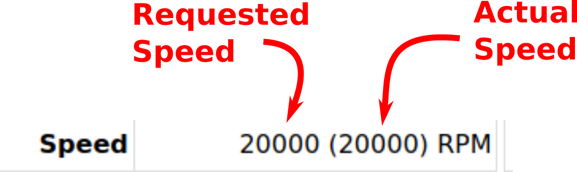
The 'Speed' field reflects the rotational speed of the spindle in revolutions per minute (RPM) as set by an executing a GCode “S” command. If the spindle is capable of reporting the actual speed of the spindle back to the Buildbotics Controller, then the actual speed is also reported in the Speed field, as shown.
The 'Remaining' field shows the amount of time required for the program that is currently loaded to complete.
The 'Line' field displays the line number that is currently being processed in a GCode program.
The 'Progress' field reflects the amount of the currently loaded GCode program that has already been executed. The value is given in percent.
Note 1 - Homing sequences are described in the 'Motors' Tab on the 'SETTINGS' Page.
Tabbed Section
The tabbed section provides controls for:
- Running GCode Programs (Auto tab)
- Manually issuing GCode Commands (MDI tab)
- Jogging (Jog tab)
- Reading detailed messages (Messages tab)
- Read the state of I/O pins on the DB25 connector I/O Pins tab
- Read power measurements and motor driver status Power tab
Auto Tab
The Auto tab provides controls for viewing and running GCode programs.
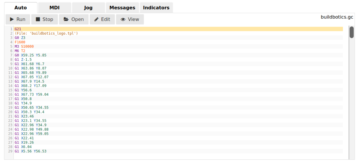
When the Auto tab is selected and no program is running, the 'Run' button, the 'Stop' button, the 'Open' button, the 'Edit' button, and the 'View' button are displayed.
Click the Run button to execute the currently loaded program. This changes the 'State' to 'Running', changes the 'Run' button to a 'Pause' button, and deactivates the 'Open' button.
Click the 'Pause' button to stop executing the currently loaded program. This changes the 'State' field to 'Holding' and changes the 'Pause' button to back to 'Run'. Click 'Run' again to resume execution from where it stopped.
Click 'Stop' to stop executing and exit from the program that is currently 'Running' or 'Holding'.
Click 'Open' to select and load a different program.
Click 'Edit' to navigate to the Editor Page and begin editing the currently loaded program.
Click 'View' to navigate to the 3D View Page to view the cut path simulation of the currently loaded program.
The program that is currently loaded is displayed in the scrolling window below the control buttons. This window will automatically scroll through the program as it is being processed and highlight the line that is currently being processed.
Users may notice that the actual cutting position lags the highlighted line. After a line is processed, it is put in a queue to be sent to the control hardware for execution.
MDI Tab
The Manual Data Input (MDI) tab allows the user to control the machine by manually entering GCode commands.
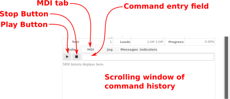
The 'Play' button causes the commands that are currently in the command entry field to be executed.
The 'Stop' button causes any commands that are currently executing to stop.
The command entry field accepts GCode commands from the user. Pressing the enter key after typing commands into the command entry field causes those commands to be executed.
The scrolling window of command history displays commands that have been executed. The most recent commands are displayed at the top. Clicking a previously executed command in the scrolling window causes that command to be loaded into the command entry field.
Jog Tab
The Jog tab allows users to jog the machine on any axis.
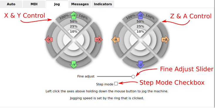
The controls operate differently depending on the mode of the interface. If the step mode checkbox is unchecked, then the axis starts moving when you left-click and hold on the control and stops moving when you release. If the step mode checkbox is checked, the axis will move a specified distance when the control is clicked.
When in 'step mode', the distance moved is determined by the ring that is clicked. Each ring is labeled with an number that specifies the distance in the current units that the axis will move when clicked.
The current units are specified in the 'Units' field in the status table.
When in 'step mode', the integer values for each ring can be adjusted using the fine adjust slider. The 'fine adjust' slider can be on the left, in the middle, or on the right. The following table shows the distance ranges available when in 'step mode'.
| Slider Position | Inner Ring | Second Ring | Third Ring | Outer Ring |
| Left | .001 | .01 | .1 | 1 |
| Middle | .01 | .1 | 1 | 10 |
| Right | .1 | 1 | 10 | 100 |
When not in step mode, the numbers on the controls represent the percent of the maximum speed for the axis at which the axis will move when left-clicking and holding. The maximum speed for the axis is set in the motor configuration.
Once again, the slider has three positions. The following table shows the percent of maximum speed that can be achieved by clicking the various rings with different 'fine adjust' settings.
| Slider Position | Inner Ring | Second Ring | Third Ring | Outer Ring |
| Left | .1% | .25% | .5% | 1% |
| Middle | 1% | 2.5% | 5% | 10% |
| Right | 10% | 25% | 50% | 100% |
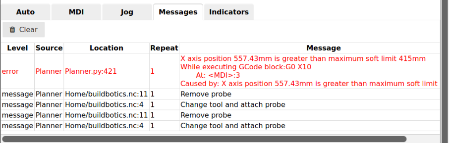
Messages Tab
The Messages tab displays a running list of error and status messages. The most recent message is appended to the bottom of the list. These messages can assist in troubleshooting problems. The Message field gives a brief description of the issue and the Location field sometimes gives the source code file and line number where the issue was encountered.
The Repeat field reports the number of times that the issue has occurred.
Clicking the Clear button deletes the list of messages.
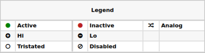
I/O Pins Tab
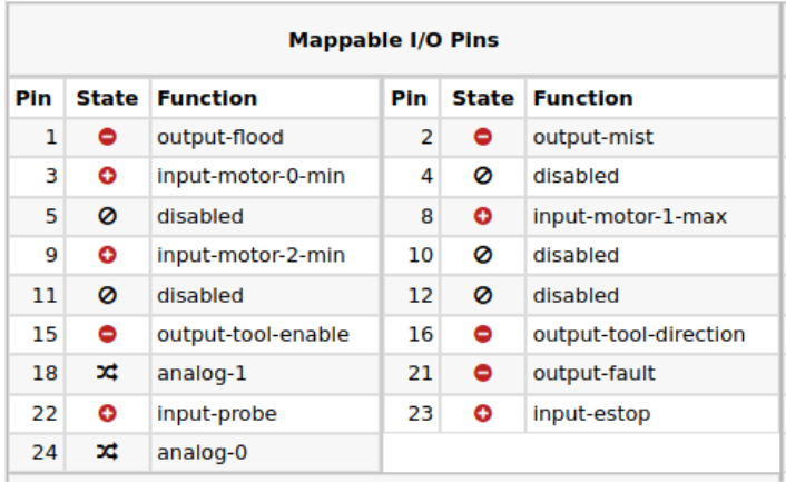
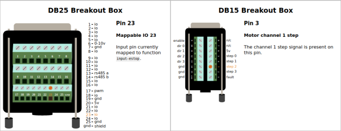
The I/O Pins tab provides a legend for the state of the pins, the Mappable I/O Pins table, and images with pin assignments for the DB25 and DB15 breakout boxes.
The Mappable I/O Pins table shows the function that is assigned to each pin on the DB25 connector. These functions are assigned on the SETTINGS Page I/O tab.
The images for the DB25 and DB15 breakout boxes show the pin assignments for each pin position. Hovering over any screw terminal on these images causes the terminal to highlight and presents a description of the function that is currently assigned to that terminal. Terminals that are mappable are assigned on the SETTINGS Page I/O tab.
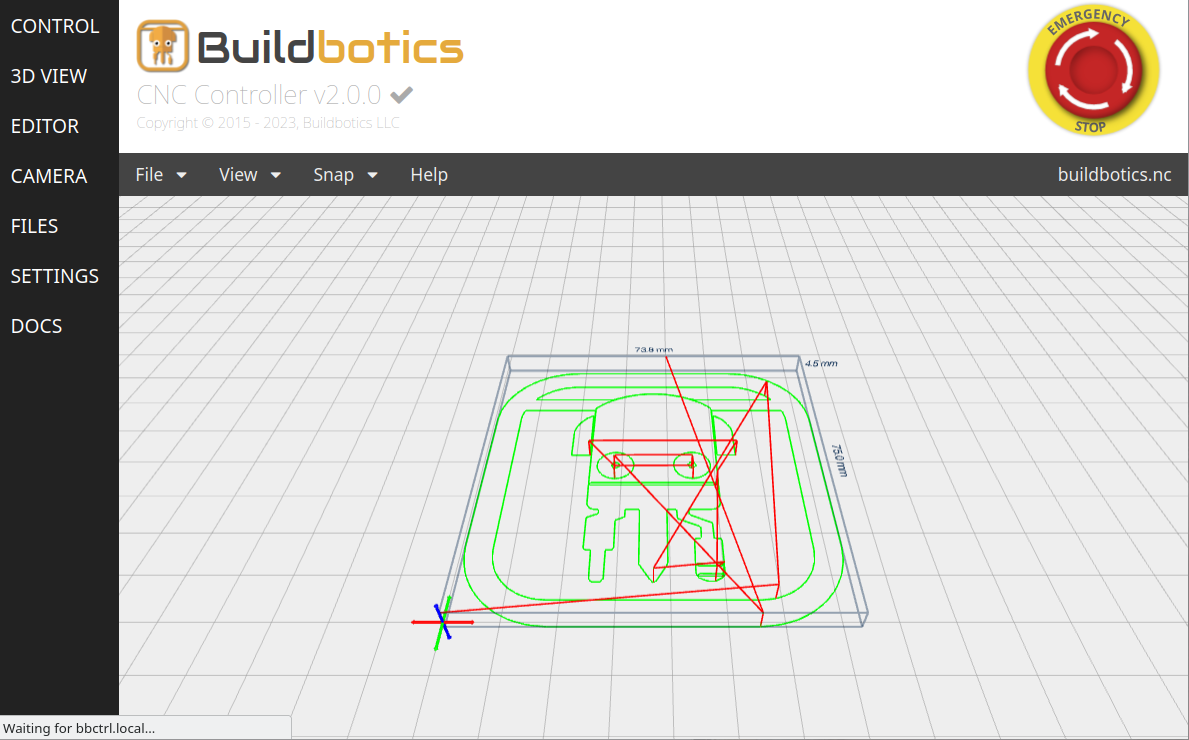
3D VIEW Page
The 3D VIEW Page displays tool paths for GCode programs. If the program that is displayed is currently running, then a real-time, animated representation of the tool moving along the tool paths is displayed.
To view a specific GCode program that has already been loaded onto the Buildbotics Controller, select File->Open and then choose the desired file from the Buildbotics Controller file system.
To upload and view a file from across the local area network, select File->Open, click 'Upload', and then select the file from your local machine.
Selecting File->Edit navigates to the EDITOR PAGE and loads the program that is currently displayed for editing.
Selecting File->Run navigates to the Control Page and runs the program that is currently loaded on the 3D View.
The View menu provides to ability to toggle graphical features on and off. These features include the tool, the grid, the axis marker, the boundaries of the tool paths, and laser raster intensity.
Enabling the 'laser raster' feature varies the shading on the tool paths in proportion with the laser intensity allowing an image to appear that is similar to the laser raster image that will be imprinted on the material surface.
The Snap menu provides the ability to view the image from several different perspectives.
The Help menu provides some useful tips on features of the 3D Viewer, as well as tips on using mouse controls to minipulate the image.
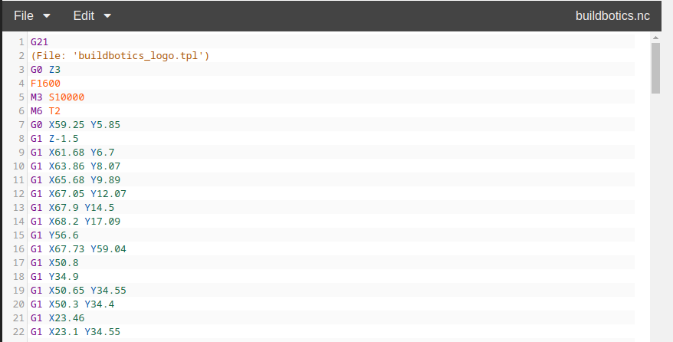
EDITOR Page
The Editor page provides the ability to create, edit, and view gcode programs from within the user interface of the Buildbotics Controller.
The File menu provides:
- New - Create a new gcode file.
- Open - Open an existing gcode file.
- Save - Save the current file.
- Save As - Save the contents to a different file.
- Revert - Undo all recent changes.
- Download - Download the current file to another location.
- View - Navigate to the 3D VIEW Page and view the cut paths of the current file.
- Run - Navigate to the CONTROL Page and run the current file.
The Edit menu provides:
- Undo - Undo the last change
- Redo - redo the last undo
- Copy - copy the selected text into a buffer
- Cut - delete the selected text
- Paste - Paste the contents of the buffer into the current cursor location
Simply click in the text area and start typing to make edits.
CAMERA Page
The CAMERA Page presents the view of a web camera that can be plugged into the back of the Buildbotics Controller.
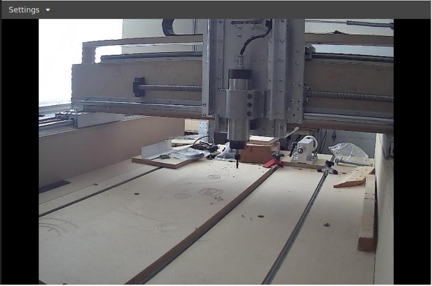
Clicking the small video window on any or the other pages, navigates to the CAMERA Page.
Select 'Show Crosshair' from the 'Settings' pull-down menu to toggle the cross hair on the video image.
FILES Page
The FILES Page provides the ability to manage files.
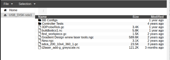
The File menu provides the ability to:
- Upload Files - Upload files from a remote computer to the Buildbotics Controller. This option does nothing if you are working from a local monitor on the Buildbotics Controller.
- New Folder - Create a new folder.
The Selection menu provides:
- Edit - Navigate the EDITOR Page to open and edit the selected file.
- View - Navigate to the 3D VIEW Page to view the cutpaths for the selected file.
- Download - Download the selected file from the Buildbotics Controller to a remote computer. This option does nothing if you are working from a local monitor on the Buildbotics Controller.
- Delete - Delete the selected file.
SETTINGS Page
Administration and configuration of the Buildbotics Controller is done from the SETTINGS Page.
Within the SETTINGS Page, there are several tabs. Each tab provides a different set of configuration or administration items. The tabs are:
- General
- Motors - This is acually a pull down menu providing access to each of the four motor ports.
- Tool
- I/O
- Macros
- Network
- Admin
Some changes require the user to log in.
Important - When an item is changed, the 'Save' button will turn green. When clicked, the 'Save' button changes back to grey. The Buildbotics Controller will not let you navigate away from the SETTINGS Page with unsaved changes.

Logging in

Users must log in before making any of the following changes:
- Change the password on the Admin Tab.
- Restore, Backup, or Reset the Controller configuration on the Admin Tab.
- Change the Username on the Admin Tab.
- Upgrade or Upload firmware on the Admin Tab.
- Change the Hostname on the Network Tab
- Connect to or disconnect from WiFi networks on the Network Tab
The default password is 'buildbotics'. Once the user has logged in, the green 'Login' button becomes a grey 'Logout' button.
General Tab
The General Tab provides the ability to set the units for configuration, define code blocks to be executed at start, end, and during tool changes, define the path accuracy, and set the limit for acceleration around corners.
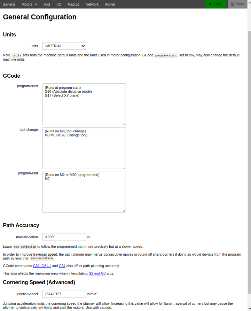
The ‘units’ pull down menu allows selecting between IMPERIAL or METRIC units. All configuration pages will display in the selected units. Additionally, the Units field on the Control Page will default to the value selected when it boots. This selection can be overridden for ‘display and operation’ on the Control Page when a G20 or G21 GCode is encountered.
Insertions of sequences of ‘G’ and/or ‘M’ codes are possible at the beginning, at the end, and during tool changes. It is often helpful to add comments to the commands. Comments are enclosed in parentheses. Some commands cause program execution to pause and wait for the user to take action before resuming execution. When the characters ‘MSG,’ are entered at the beginning of the comment, the remainder of the comment is presented to the user in an “action dialog”. This helps instruct the user on what action to take before resuming execution.
G and M code commands entered in the “program-start” entry box will be inserted at the beginning of GCode programs when they are executed. By default, the following GCode commands are entered in the “program-start” entry box.
(Runs at program start)
G90 (Absolute distance mode)
G17 (Select XY plane)
Similarly, the “program-end” entry box contains commands that will be inserted at the end of GCode programs. By default, the following GCode commands are entered in the “program-end” entry box.
(Runs on M2, program end)
M2
The “tool-change” entry box contains commands that are run every time an M6 (tool change) command is encountered. By default, the “tool-change” entry box contains the following commands:
(Runs on M6, tool change)
M0 M6 (MSG, Change Tool)
These commands simply pause execution and prompt the user to change the tool. The following example provides a set of commands that can be used to change the tool and then set the height of the z-axis after the tool change. This example assumes the use of a 0.75” (19.05mm) touch plate like the one shown here.
(Runs on M6, tool change)
M70
G21
G0Z100
M0 (MSG, Change tool and attach probe)
F100
G91
G38.2 Z-100
G92 Z19.05
G0 Z25
M0 (MSG, Remove probe)
M72
M70 tells the controller to save its current state (e.g. feed rate, distance mode, and units) so it can be recovered after the sequence is completed.
G21 tells the controller to operate in Metric units.
G0 Z100 raises the tool to 100mm so the tool can be replaced.
M0 (MSG, Change tool and attach z-probe) - The comment starts with ‘MSG,’ so the text “Change tool and attach z-probe” is presented to the user in the action dialog.
F100 says that the feed rate will be 100 mm/minute. This feed rate should be slow to prevent jamming the bit into the surface of the probe. Ideally, the search will stop at the instant that the bit touches the probe.
G91 puts the machine in "incremental distance mode" so it will probe downward by 100mm or until the probe is found in the next command.
G38.2 Z-100 tells the machine to move towards the probe and stop when the probe surface is found. If the search reaches Z = -100 without finding the probe surface, the search will stop and the probing command fails.
G92 Z19.05 sets the z axis to 19.05mm, which is the height of the probe base being used in this example.
G0 Z25 tells the machine to move up to Z = 25 so the probe can easily be removed.
M0 (MSG, Remove probe) reminds the user to remove the probe and waits for the user to click “Continue” to resume execution of the GCode program.
M72 restores the original state (e.g. feed rate, distance mode, and units) that existed at the beginning of the tool change procedure.
The 'max-deviation' entry box sets the Path Accuracy. This defines how much the Buildbotics Controller is allowed to round off corners and defines the maximum allowable deviation when interpolating arcs. Setting this number too low will cause the machine to run slowly. The default value is 0.1mm. This value can be overriden in GCode programs using the G61, G61.1, and G64 GCode commands.
The 'junction-accel' entry box sets the maximum allowable centripedal acceleration around corners. Increasing this value will allow for faster traversal of corners but may cause the planner to violate axis jerk limits and stall the motors. Use with caution.
Motors Tab
The Buildbotics Controller has four motor ports labeled M0, M1, M2, and M3 respectively. Select the individual motor port from the Motor Tab pull down menu.
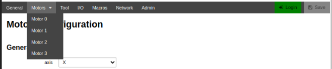
The Motor Configuration Tab provides all configuration items specific to the selected port.
The MotorConfiguration Tab is subdivided into sections titled 'General', 'Driver', 'Power', 'Motion', 'Limits', and 'Homing'.
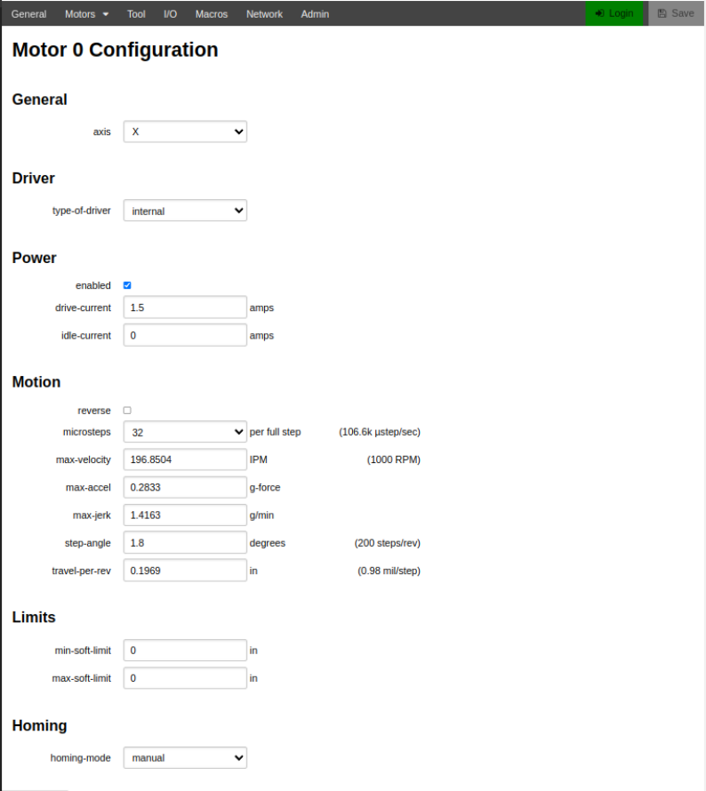
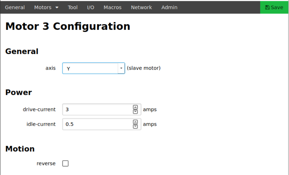
General
Within the 'General' section, select the axis to be assigned to the motor port from the 'axis' pull-down menu. Axis X, Y, Z, A, B, or C can be assigned to any motor port.
An axis can be assigned to more than one port. When an axis is assigned to a second port, only the 'drive-current', 'idle-current', and 'reverse' fields can be configured for that subsequent motor port. The remaining fields are inherited from the first motor port assigned to that axis.
Driver
The 'type-of-driver' pull-down menu allows selecting between 'internal' or 'external' drivers.
If 'internal' is selected the 'step-length' is set to .000002 seconds to match the needs of the internal drivers and the 'step-length' field is not displayed.
If 'external' is selected, the 'step-length' field is set by the user. This field should be set to match the step length requirement of the external driver being used.

Power
The “Power” section configures the amount of current that will flow to the motors.
Check “enabled” to enable the axis. Only 'enabled' axes will appear in the Axis Table on the Control Page.
The drive-current entry box sets the maximum peak current in amps that is supplied to each motor coil. Users should look up this value on the motor data sheet. When connecting two motors in parallel on a single port, the maximum current should be set to double that shown in the motor data sheet. The drive current setting cannot be greater than 6 Amps.
The idle-current entry sets the peak holding current in amps that is supplied when the motor is not moving. In many cases, this can be set to zero. Some systems may require a value that is greater than zero to ensure that the motor holds its position when not moving. The maximum idle-current that can be assigned is 2 amps.
Motion
The “Motion” section sets the speed and direction of the motor.
Checking the reverse checkbox causes the axis to move in the opposite direction.
The microsteps pull-down menu sets the level of microstepping to be used for this axis. Microstepping allows smoother and more accurate motion by subdividing motor steps. For instance, setting microstepping to 32 subdivides each motor step into 32 microsteps. Selections available for microsteps per step include 1, 2, 4, 8, 16, 32, 64, 128, and 256.
Since the maximum step rate is 250,000 steps per second, the maximum velocity may be limited at the highest microstep settings. Maximum velocity will automatically adjust if the maximum step rate is exceeded. Users should verify that the maximum velocity is still correct after adjusting microstepping. If not, users should consider lowering the number of microsteps.
In most cases, setting microstepping to 32 is a good balance.
The number of microsteps per second that will be generated at the maximum velocity is displayed to the right of the microsteps pull down menu.
The maximum-velocity entry box sets the maximum speed at which the axis will move. Typically, users will want this value to be as high as possible without experiencing motor stalls.
A good practice is to experiment with your machine to determine the maximum velocity for each axis, and then set the maximum velocity to about 80% of that value for the actual use of the machine. Note, this is the speed at which rapid moves will occur on your machine. Cutting feed rates are set in GCode and will typically be less than the maximum velocity set in the maximum velocity entry box. The axis will not move at a rate greater than this value even if the feed rate set in GCode is greater than the value set here.
Often times, stepper motor data sheets provide speed versus torque curves with speed shown in revolutions per minute (RPM). The field just to the right of the max-velocity field calculates the motor RPM at maximum velocity based on the maximum velocity, the step angle, and the travel per revolution.
The max-acceleration field sets the maximum acceleration. Excessive acceleration will cause your motors to stall during acceleration or deceleration. Insufficient acceleration will increase cutting time. Experimentation will help you find the optimum value for this field. Metric units for acceleration are given in kilometers per minute2 (km/min2). Imperial units for acceleration are given in “g’s” where one g is the acceleration of gravity (32 feet per second2).
The maximum-jerk entry box sets the amount of jerk that the axis will experience when changing from one velocity to another. Jerk is the rate of change of acceleration. The Buildbotics Controller provides smooth S-curve acceleration and this value sets the rate of change of acceleration. Higher jerk values will cause acceleration to change more abruptly and potentially cause the axis to jerk at the beginning and end of acceleration periods. These jerks can cause the machine to move. The jerk entry box allows users to maximize acceleration rates while minimizing jerks. Metric units for jerk are given in kilometers per minute3 (km/min3). Imperial units for jerk are given in g’s per minute (g/min).
The step-angle entry box sets the step angle in degrees that the motor turns with each full motor step. Users should consult the motor data sheet to determine this value. Most modern stepper motors have 200 steps per revolution, or 1.8° per step. If this is the case, enter 1.8 in the step angle entry box. The field to the right shows the number of steps per revolution for the step angle given.
The travel-per-revolution entry box tells the controller how far the axis will move with each revolution of the motor. The field to the right shows how far the axis will move with each full step. This is a function of the gear ratio of the motor, the number of steps per revolution, and the pitch of the pinion belt, lead screw, or ball screw used to move the axis.
Example - An axis having a ball screw with 2.5 millimeters per turn that is driven by a 10-to-1 gear reduction would move 2.5 x .1 = 0.25 millimeters per turn.
Example - An axis that is driven by a belt and pinion system where the belt pitch is 3 millimeters per tooth and the motor pulley has 20 teeth would move 60 millimeters per revolution.
Example - An axis that uses an 8 millimeter pitch lead screw that is directly driven by the stepper motor would travel 8 millimeters for each revolution.
Limits
The “Limits” section sets soft limits for the axis.
The min-soft-limit entry box sets the minimum absolute position for the axis. If the machine is homed, movements below this position will not be allowed.
The max-soft-limit entry box sets the maximum absolute position for the axis. If the machine is homed, movements above this position will not be allowed.
Homing
The “Homing” section sets the homing procedure for the axis.
The 'homing-mode' pull-down menu sets the method used for homing the axis. The choices are:
- manual
- switch-min
- switch-max
Manual Homing
The axis is manually homed by the user. If manual homing is selected, no other homing configuration fields are presented.
In manual homing mode, the user homes the axis by clicking the 'Home' button for that axis in the Axis table on the Control Page. The Controller responds by prompting the user to enter an 'Absolute' position and sets the Absolute and Position fields in the Axis table to the value entered by the user. The Offset in the Axis table is set to 0.
Switch-min and Switch-max Homing
Switch-min and switch-max homing rely on limit switches that are connected to inputs on the DB25 connector. These inputs must be configured on the I/O tab on the SETTINGS Page.
When homing in the 'switch-min' homing mode, the axis will travel towards its minimum position until the limit switch at the minimum position is activated. In this mode, the Position and Absolute fields in the Axis table are set to the value in the 'min-soft-limit' field and the Offset field in the Axis table is set to zero.
When homing in the 'switch-max' homing mode, the axis will travel towards its maximum position until the limit switch at the maximum position is activated. In this mode, the Position and Absolute fields in the Axis table are set to the value in the 'max-soft-limit' field and the Offset field in the Axis table is set to zero.
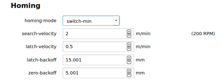
When the homing-mode is 'switch-min' or 'switch-max', the following additional configuration fields are presented:
- search velocity
- latch velocity
- latch-backoff
- zero-backoff
The following sequence describes the actions taken when homing is initiated on an axis that uses 'switch-min' or 'switch-max' homing.
- The axis travels toward the switch at the velocity that is set in the 'search-velocity' field.
- When the switch is found, the axis backs away from the switch until the switch de-activates or the distance defined in the 'latch-backoff' field is reached. If the 'latch-backoff' distance is reached before the switch de-activates, the homing sequence fails and is aborted.
- When the switch deactivates during the 'latch-backoff' step, the axis once again approaches the switch at the velocity specified in the 'latch-valocity' field.
- When the switch activates a second time, the axis backs away from the switch by the distance defined in the 'zero-backoff' field.
- The Position and Absolute fields in the Axis table are set to the 'soft-limit' and the Offset field is set to zero. The state of the axis is set to 'HOMED'.
Tool Tab
Select the 'Tool' tab on the SETTINGS Page to configure spindles or lasers.
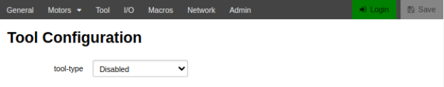
The fields in the Tool Configuration screen differ depending on the value selected in the 'tool-type' pull-down menu.
If the Buildbotics Controller does not control a spindle, set the ‘tool-type’ pull down menu to “Disabled”. When the spindle is “Disabled”, no other fields are present.
When ‘tool-type’ is not ‘Disabled’, the tool configuration is displayed in two sections. The fields in the upper section are common to all tool types.
The tool-type pull-down menu selects the tool type. The defined tool types are:
- Disabled - No spindle is controlled by the Buildbotics Controller
- PWM Spindle - Uses spin enable and direction pins, and PWM or 0-10 Volt analog signals to control the spindle. (1) (4)
- Huanyang VFD (2)
- Custom Modbus VFD - Users specify the register settings for their particular MODBUS VFD. (2)
- AC-Tech VFD (2)
- Nowforever VFD (2)
- Delta VFD015M21a (Beta) (2), (3)
- YL600, YL620, YL620A VFD (Beta) (2), (3)
- FR-D700 VFD (Beta) (2), (3)
- Sunfar E300 (Beta) (2), (3)
- OMRON MX2 (2)
- V70 (2)
- H100 (2)
- WJ200 (2)
- DMM DYN4 (Beta) (2), (3)
- Galt G200/G500 (2)
- Teco Westinghouse E510 (2)
- EM60 (2)
- Fuling DZB200/300 (2)
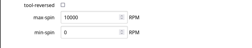
The other common fields are:
- ‘tool-reversed’ checkbox - Checking ‘tool-reversed’ causes the spindle to turn in the opposite direction. For instance, if an M3 GCode command causes the tool to turn clockwise when ‘tool-reversed’ is not checked, then the tool would turn counter-clockwise when an M3 command is issued and ‘tool-reversed’ is checked.
- ‘max-spin’ - tells the controller how fast the spindle turns (in RPM) when the maximum speed is specified.
- ‘min-spin’ - tells the controller how fast the spindle turns (in RPM) when the minimum speed is specified.
Note 1 - Refer to the PWM Connections Section for information about connecting a PWM Spindle.
Note 2 - For all tool types except for PWM Spindle, the spindle is controlled through a VFD and connects to the RS-485/Modbus. Refer to the RS485 Connections Section for information on connecting a Modbus VFD. The Modbus commands, registers and register addresses are unique to each type of Modbus VFD.
Note 3 - VFD types that are marked (Beta) are still in development and have only been partially tested. Let us know your experiences with these interfaces.
*Note 4 - Refer to the 0-10 Volt Analog Connections Section for information about connecting a 0-10 Volt analog speed controlled Spindle.
PWM Spindle
The PWM Spindle uses the PWM output or the 0-10 Volt analog output and the spin enable and spin direction mappable outputs to control the spindle or laser. These outputs are all provided on the DB25 output connector on the back panel. The spin-enable and spin-direction functions must be assigned to mappable output pins on the I/O Tab on the SETTINGS Page.
The tool type must be set to PWM Spindle if spin-direction and spin-enable pins on the DB25 connector are required even if the spindle speed is not controlled.
Within the Buildbotics Controller, the 0-10 Volt analog circuitry is driven by the PWM output. The resulting output voltage on the 0-10 Volt analog output will simply be 10 Volts times the percent of time that the PWM signal is high (i.e. the duty cycle of the PWM signal if it is not inverted).
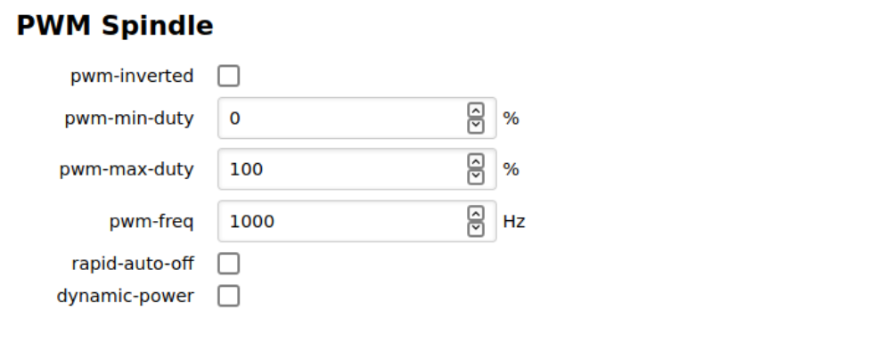
The following fields are provided when ‘PWM Spindle’ is selected in the ‘tool-type’ drop-down menu.
- ‘pwm-inverted’ - When checked, the ‘pwm-inverted’ checkbox causes the duty cycle fields to mean the percent of time that the PWM output is at a logic low. When unchecked, it causes the duty cycle fields to mean the percent of time that the PWM output is at a logic high.
- ‘pwm-min-duty’ - The ‘pwm-min-duty’ field specifies the percent of time that the “Tool PWM” pin on the DB25 I/O connector will be active when the spindle is turning at the rate specified in the ‘min-spin’ field. The “active” state is specified by the ‘pwm-inverted’ checkbox.
- ‘pwm-max-duty’ - The ‘pwm-max-duty’ field specifies the percent of time that the “Tool PWM” pin on the DB25 I/O connector will be active when the spindle is turning at the rate specified in the ‘max-spin’ field. The “active” state is specified by the ‘pwm-inverted’ checkbox.
- ‘pwm-freq’ - The ‘pwm-freq’ field specifies the rate (in Hertz) at which PWM pulses are sent out through the “Tool PWM” pin on the DB25 I/O connector.
- 'rapid-auto-off' - Checking the 'rapid-auto-off' checkbox causes the cutting head to be turned off during rapid moves. This should only be used if the cutting head can be turned off and on instantaneously. This field is mainly used for laser cutters and engravers.
- 'dynamic-power' - Checking 'dynamic-power' automatically lowers the cutting head power during acceleration and deceleration. Once again, this setting is mainly used for laser cutters and engravers. With this setting enabled, the intensity of the laser is reduced until the full speed is reached. This prevents having excess energy deposited during acceleration and deceleration. Otherwise, the excess energy could result in over-exposed or burned areas in laser engraved images.
Most VFD's can be controlled using the "Tool Enable", "Tool Direction", and "Spin0-10" pins on the DB25 connector. However, Buildbotics recommends using the RS485 interface for the specific VFD if it is provided.
RS-485/Modbus Spindles
This section describes the additional fields provided for RS-485/Modbus driven spindles.
Modbus Configuration Section
The 'Modbus Configuration section is presented for all RS-485/Modbus driven spindles.

'bus-id' establishes the communications address on the RS485 connection. Set the value in this field to match the communications address in the VFD.
'baud' should match the setting in the VFD.
'parity' should match the setting in the VFD and will usually be set to none.
Modbus Status Section
The 'Modbus Status section is presented for all RS-485/Modbus driven spindles.

The Modbus Status section displays the state of the RS-485/Modbus connection to the VFD.
The 'connection' field shows the state of the connection. The following states are possible:
- Disconnected - The VFD is not connected to the Buildbotics Controller or the wiring is incorrect.
- Timedout - The VFD may be connected to the Buildbotics Controller but communications has not been established. The likely cause is the bus-id, parity, or baud rate do not match or the registers are not set correctly in the VFD.
- Ok - The communications link is working properly.
The 'status' field displays an integer that is fed back from the VFD and provides information about the current state of the VFD. Refer to the manual for the specific VFD to interpret the number that is displayed.
The 'speed' field displays the speed of the spindle in RPM.
Active Modbus Program Section
The Active Modbus Program section is presented for all VFD Driven spindle types except for Huanyang.
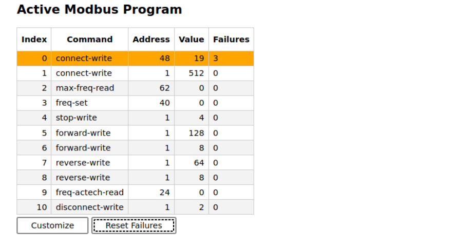
The table displays the Modbus program for the current VFD. The column definitions are:
- Index - This is essentially the line number of the program.
- Command - This is the action that will be taken on the Modbus interface. The possible commands are described in the Edit Modbus Program Section.
- Address - This is the address of the Modbus register in decimal numbers.
- Value - This is the value that will be written to the Modbus register. The value is always zero for read commands.
- Failures - This is a running count of the number of times a specific command has been attempted and failed. If the maximum mumber is reached, 'Max' will be displayed. Click 'Reset Failures' to reset the failure count to zero.
Clicking 'Customize' changes the 'tool-type' to 'Custom Modbus VFD' and presents the Edit Modbus Program Section to allow editing the existing program.
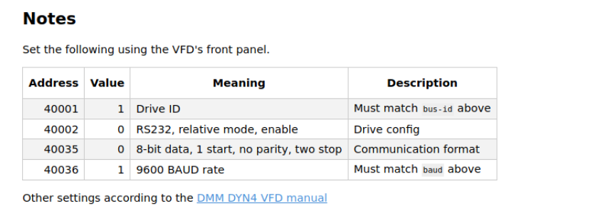
Notes Section
All VFD tool types except for AC-Tech VFD and FR-D700 (Beta) provide a notes section at the bottom of the page. The notes include a table that lists the recommended VFD register settings and a link to the respective VFD manual.
Custom Modbus VFD
The Custom Modbus VFD selection from the 'tool-type' menu provides the ability to create a new and unique VFD interface. Users can select this tool-type from the menu to start from scratch. It is often better to select a VFD that is similar to the one being created. After the similar VFD is selected and "Saved", Click 'Customize' from the Active Modbus Program to navigate to the 'Custom Modbus VFD' tool type and transfer the program in the similar VFD to the new custom VFD.
The Custom Modbus VFD tool-type adds a 'Clear' button to the Active Modbus Program Section. Click this button to clear all commands from the Edit Modbus Program table.
Edit Modbus Program Section
The Custom Modbus VFD tool-type presents the Edit Modbus Program section.
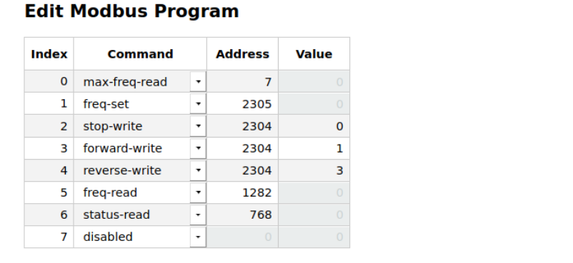
The columns in the Edit Modbus Program table are:
- Index - This is essentially the line number of the program.
- Command - This is the action that will be taken on the Modbus interface.
- Address - This is the address of the Modbus register in decimal numbers.
- Value - This is the value that will be written to the Modbus register. The value field is only active for commands that write to Modbus registers.
Commands in the 'Command' column are selected from a pull-down menu. The commands and their descriptions are:
- disabled - This command is disabled and will be ignored
- connect-write - This command is used to connect to the VFD and prepare it for accepting other Modbus commands.
- max-freq-read - Read the maximum frequency setting. This value is used to as a multiplier when setting or reading the actual speed.
- max-freq-fixed - Hard code the maximum frequency of the VFD rather than reading it from the drive using 'max-freq-read'. This value is used to as a multiplier when setting or reading the actual speed.
- freq-set - Set the frequency of the VFD. This value sets the speed of the spindle based on the maximum frequency.
- freq-signed-set - Some VFD's use a negative frequency for reverse direction. This paramater sets the speed based on the maximum frequency and sets direction of the spindle based on the sign.
- freq-scaled-set - Some VFD's expect a scaled number when setting the speed. freq-scaled-set provides an argument that can be used to scale the speed requested to match the requirements of the VFD. The argument is entered in the 'Value' column.
- stop-write - Commands the VFD to stop the spindle.
- forward-write - Commands the spindle to spin in the forward direction.
- reverse-write - Commands the spindle to spin in the reverse direction.
- freq-read - This command reads the current speed of the spindle.
- freq-signed-read - This command is unique to the AC-Tech spindle and reads the current speed and direction of the spindle.
- freq-actech-read - This command is unique to the AC-Tech spindle and reads the current speed of the spindle.
- status-read - Read the status of the VFD. See the VFD manual to see what values might be returned. This value is displayed in the status field in the Modbus Status section.
- disconnect-write - Disconnect from the VFD.
Some commands require multiple lines in the Edit Modbus Program table. In this case, simply place the two commands consequitively in the table with the same command name.
I/O Tab
Select the I/O tab from the Settings page to configure the I/O pins on the DB25 connector. The table in the 'Remappable Pins' section is used to configure and display the state of each I/O pin. The 'Input' section is used to mask noise and switch bounce.
Remappable Pins
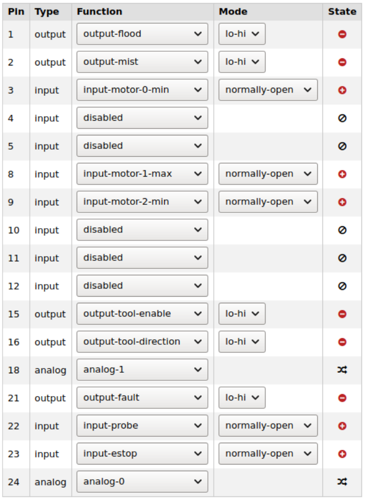
The columns in the table are:
- Pin - specifies the pin number
- Type - specifies the pin type. The possible types are 'output', 'input', and 'analog'. (1)
- Function - The pull-down menus provide specific functions that are available depending the pin type.
- Mode - The pull-down menus specify the signal types that are available for the pin type.
- State - displays the state for of the pin. The states are described in the legend on the Idicators Tab on the Control Page
Output pins
The possible functions for remappable 'output' pins are:
- disabled - disabled pins are not used
- output-0, output-1, output-2, output-3 - these functions are not currently used.
- output-flood - Normally used for turning on and off flood coolant. This output is controlled with M8, M8.1, and M9 GCode commands.
- output-mist - Normally used for turning on and off mist coolant. This output is controlled with M7, M7.1, and M9 GCode commands.
- output-tool-enable - Normally used for turning the spindle on and off. This output is controlled by the M3 and M5 GCode commands.
- output-tool-direction - Normally used for specifying the direction that the spindle will turn. This output is controlled the the M4 GCode command.
The possible 'Modes' for output pins are:
- “lo-hi” means the pin switches from a logic low to a logic high to indicate that the pin has activated.
- “hi-lo” means the pin switches from a logic high to a logic low to indicate that the pin has activated.
- “tri-lo” means the pin switches from a high impedance state to a logic low to indicate that the pin has activated.
- “tri-hi” means the pin switches from a high impedance state to a logic high to indicate that the pin has activated.
- “lo-tri” means the pin switches from a logic low to a high impedance state to indicate that the pin has activated.
- “hi-tri” means the pin switches from a logic high to a high impedance state to indicate that the pin has activated.
Input Pins
The possible functions for remappable 'input' pins are:
- disabled - disabled pins are not used
- input-motor-0-min - lower limit switch input for the axis that is assigned to motor port 0
- input-motor-0-max - upper limit switch input for the axis that is assigned to motor port 0
- input-motor-1-min - lower limit switch input for the axis that is assigned to motor port 1
- input-motor-1-max - upper limit switch input for the axis that is assigned to motor port 1
- input-motor-2-min - lower limit switch input for the axis that is assigned to motor port 2
- input-motor-2-max - upper limit switch input for the axis that is assigned to motor port 2
- input-motor-3-min - lower limit switch input for the axis that is assigned to motor port 3
- input-motor-3-max - upper limit switch input for the axis that is assigned to motor port 3
- input-0, input-1, input-2, input-3 - These functions are not currently used.
- input-estop - This function is used for an estop switch. Note, this function is software controlled and should not be used for 'life safety' or 'mission critical' purposes.
- input-probe - This function is used for a 'probe' input. It is normally used in conjunction with G38.2 through G38.5 straight probe GCode Commands.
The possible modes for the inputs are:
- Normally Open - The input is active when pulled to ground.
- Normally Closed - The input is active when not pulled to ground.
Analog Pins
Analog pins are not currently used.
Input
The "Input" section configures switch-debounce time and switch-lockout time. Switch debounce is the time in milliseconds before a switch state change is recognized. Switch lockout is the time in milliseconds before the state can change again after a state change has been recognized. (2).
Note 1 - Non-configurable pins are not included in the 'Remappable I/O pins table. The following pins are not shown:
- Ground pins - pins 7, 19, 25, and the shield on the DB25 connector.
- Power pins - pin 20
- Pins with dedicated functions - Pin 6 (0-10V) and pin 17 (pwm)
- Pins on the DB15 connector - None of the pins on the DB15 Auxilliary I/O connector are configurable. Their specific functions are described in the 15-Pin Auxilliary I/O Connector section of this manual
Note 2 - the settings of "switch-debounce" and "switch-lockout" affect all switch inputs on the DB25 connector.
Macros Tab
The Macros Tab on the SETTINGS Page is used to assign GCode programs to macro buttons that appear in the Macros section of the Control Page.
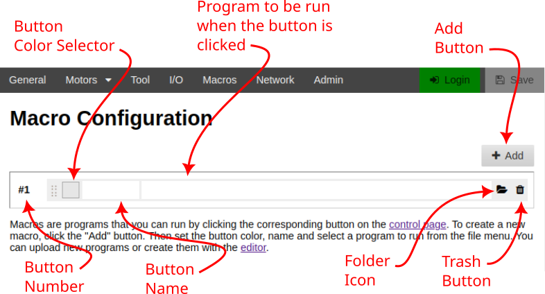
To create a new macro, click the Add button, select the color of the button and give it a name. Then, click the folder icon to select a program that will be assigned to the button. Finally, click 'Save'. A new button will appear in the Macros section of the Control Page with the color and name that was defined.
To remove a Macro button, click the trash icon and the click "Save".
To change the name of the button, simply type a new name in the button name field. To change the color, click on the color selector and pick a new color. To assign a different program, click the folder icon and choose a different program.
To edit the behavior of the existing program, navigate to the Files Page, select the program, and select Edit from the Selection menu.
Network Tab
The Network Tab on the SETTINGS Page sets the controller host name and establishes wireless network connections. The user must be logged in to make changes on this page.
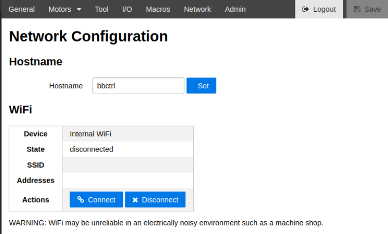
The Hostname field displays the name of the Buildbotics Controller. The default name is “bbctrl”. This name can be used to access the Buildbotics Controller using a web browser by entering the value in the Hostname field appended with “.local” in the address bar of a web browser (1). The hostname can be changed by entering a new name in the Hostname field and clicking the “Set” button. Clicking the set button causes the Buildbotics Controller to reboot.
The device shown in the WiFi section represents the internal Wifi antenna that is built into the Buildbotics Controller. If a compatible USB WiFi antenna is plugged into one of the USB ports, a second device is presented and labled 'USB WiFi').
Clicking 'Connect' presents a list of available networks similar to this.
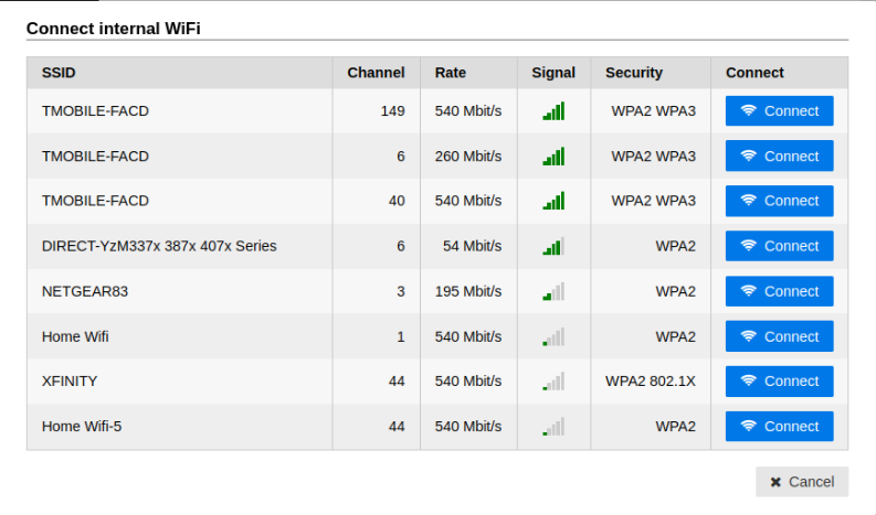
Join a network by clicking the 'Connect' button associated with that network. Then, enter the password for that network (2).
Click 'Disconnect' to disconnect from a network.
Once connected, the SSID and the IP address(es) assigned to the Buildbotics Controller will be displayed in the WiFi box.
Note 1 - Some computers may not support the hostname.local address and require that the IP address be entered into the address bar.
Note 2 - If you don't know the network password, contact the network administrator.
Admin Tab
Select the Admin tab on the SETTINGS Page to change the password for the Buildbotics Controller, backup, restore or reset the configuration, upgrade software versions, view system logs, create bug reports, and enable or disable the virtual keyboard,.
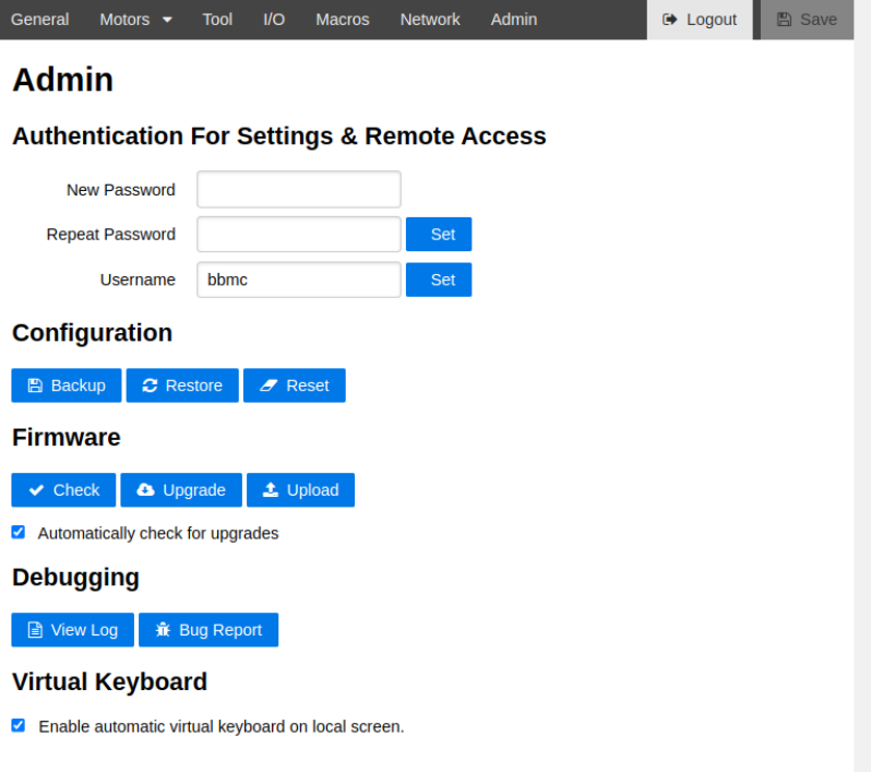
Athentication for Settings and Remote Access
The Username field contains the name of the user that can connect to the Buildbotics Controller using a SSH connection. The default value is “bbmc”.
The password fields allow changing the password for accessing the Buildbotics controller via a SSH connection and for upgrading the software. The default password is “buildbotics”. You can change the password by entering the new password twice, and then clicking the “Set” button. You must be logged in to change the password.
Caution - Use caution when changing the password. If you forget the password, it cannot be recovered in the field.
To access the Buildbotics Controller using the default username and password, open a terminal and enter the following command:
you@host: ssh bbmc@bbctrl.local
password: buildbotics
Configuration
The Configuration section allows backing up and restoring the configuration of the Buildbotics Controller. This is useful if you run your machine in multiple configurations. For instance, you may want to switch your machine configuration between a router and a laser cutter. This allows you to save a configuration for each and restore the configuration as needed.
Click “Backup” to save all configuration information to a file on your local computer.
Click “Restore” to restore a previously saved backup file.
Click “Reset” to reset the entire configuration to the factory default values
Firmware
The Firmware section allows checking, upgrading, or uploading firmware for the Buildbotics Controller.
Click “Check” to see if a new version of firmware is available.(1) If the Buildbotics Controller is already at the latest version, a “check mark” will show in the page header.
If a firmware upgrade is available, the header on all pages will show that the new firmware is available.(1) Clicking the orange link will jump to the Admin tab on the SETTINGS Page.
If the 'Automatically check for upgrades' checkbox is checked, the Buildbotics Controller will automatically check for upgrades without clicking the 'Check' button.(1)
Click “Upgrade” to upgrade to the latest version of Buildbotics Controller firmware. (2)
Click “Upload” to upgrade the Buildbotics Controller firmware from a file on the local computer. All versions of Buildbotics Controller (Raspberry Pi 4) firmware are available here. Take caution when uploading beta release or old firmware versions, as they could cause an unrecoverable failure. It is strongly advised that you contact Buildbotics support personnel through the Buildbotics Forum before attempting to upload firmware versions other than the current release.
Note 1 - The Buildbotics Controller cannot check for upgrades if no Internet service is provided.
Note 2 - Internet access is required for Upgrades. If Internet access is not available, use Upload.
Virtual Keyboard
Uncheck the 'Enable automatic virtual keyboard on local screen checkbox to prevent it from popping up each time you 'click' in a text entry field. Users with hardware keyboards are likely to uncheck this checkbox.
If the checkbox is unchecked, the virtual keyboard will still be accessible by clicking the keyboard icon at the top middle of the screen.
The virtual keyboard is only available on the local monitor. Users that need a virtual keyboard on network connections, should install a virtual keyboard on their local computer or on their web browser.
Debugging
The “Debugging” section provides the ability to view the system log and generate bug reports.
Click "View Log" to view the current log.
Click "Bug Report" to generate a report on the state of the system. You may be asked to generate a "Bug Report" by Buildbotics personnel when troubleshooting a problem. "Bug Report" creates a file that contains the system log files, the configuration of the controller, and the GCode program that is currently loaded. Simply attach the resulting file to an e-mail message to the Buildbotics support person when asked to do so.
DOCS
Select the DOCS Page to get additional information, to access a list of supported GCodes, and to review license information related the Open Source design of the Buildbotics Controller.
Help Tab
The 'Help' tab provides links to several sources of information, including our forum and this manual.
These links are only accessible if the Buildbotics Controller is attached to the internet.
GCode Tab
Select the GCode tab to access the GCode Cheat Sheet, which provides brief descriptions for all supported G and M codes. More detailed descriptions can be accessed by clicking on the commands. The detailed descriptions are actually provided through the linuxcnc.org web site, and are only accessible if internet access is available.
Check the "Show unsupported codes" checkbox near the bottom of the page to display all GCodes including those that are not supported by the Buildbotics Controller.
The "Further GCode Programming Documentation" section provides links to more information about GCode programming.
License Tab
Select the License tab for links to the Buildbotics design information, and a link to our Open Source licence.
Specifications
Enclosure Dimensions

Physical and Electrical
| Minimum | Maximum | Units | |
|---|---|---|---|
| Weight | 1 | kilogram | |
| Height | 71 | millimeters | |
| Width at base | 190 | millimeters | |
| Width | 159 | millimeters | |
| Temperature | 0 | 32 | °C |
| Humidity | 0 | 90 | % |
| Input Voltage | 24 | 48 | Volts DC |
| Motor Current | 6 | Amps | |
| Step Rate | 250000 | Steps per second | |
| Microstepping | 1 | 256 | microsteps/step |
| Input current | 15 | Amps | |
| Total output current | 15 | Amps | |
| Motor coil resistance | 0.6 | Ohms | |
| Motor coil inductance | 1 | 20 | mill-Henries |
| Rotor inertia | 2700 | gram*cm2 |
Troubleshooting
Here is a list of problems that could occur. If these suggestions don’t help resolve the problem contact us.
LCD screen doesn’t light up
- Power supply not plugged in
- Power supply not turned on
- Power supply not properly connected to Buildbotics Controller
- Enable switch on Buildbotics Controller not switched to “Enable” (up)
- Buildbotics Controller may be defective.
LCD screen lights up, but doesn’t boot
- Buildbotics Controller may be defective
Gamepad doesn’t work correctly
- Confirm that USB Gamepad is plugged into one of the USB ports on the back of the Buildbotics Controller.
- Try rebooting the Buildbotics Controller by switching the enable switch off and then back on (down and then up).
- Confirm that the gamepad is compatible with the Buildbotics Controller
- The gamepad may be defective.
- The Buildbotics Controller may be defective.
Can’t access the controller from a web browser
- Verify that the Buildbotics Controller is fully booted. “Ready” should display in the upper-left corner of the LCD screen.
- Verify that the web browser is running from a computer that is attached to the same local area network as the Buildbotics Controller. Remote access across the internet is not supported.
- Verify that the local router is turned on.
- Verify that the computer and the Buildbotics Controller are both connected to the local area network.
- Use the gamepad on the Buildbotics Controller to scroll to the LCD network screen and verify that the hostname and the IP address are displayed. If no IP address is displayed, the Buildbotics Controller is not communicating with the local router, check the network connections again or contact your network administrator.
- Verify that the hostname on the controller is the same name that is being used (with the .local extension) in the address bar of the browser.
- Try entering the IP address from the Buildbotics Controller in the address bar of the browser. There are some cases where the Buildbotics Controller can only be accessed using the IP address.
- Try pinging the IP address. If you are able to successfully ping the Buildbotics Controller but cannot access it via a web browser, the Buildbotics Controller may be defective.
Motor doesn’t move
- Verify that the motor cable is plugged into the proper motor port on the Buildbotics Controller.
- Verify that the motor wires are connected to the motor.
- Verify that the motor wiring is correct.
- Verify that the motor is properly assigned to a motor axis.
- Verify that the motor axis is properly configured.
- Verify that the controller is not in “Emergency Stop”.
- Verify that no limit switches are activated. If a limit switch is active, try disabling it.
- Confirm that all limit switches are deactivated and try rebooting.
- Check for faults in the Power Faults table. If faults are found, make changes as suggested in the description of the Power Faults table in the Indicators tab of the Control page.
- Buildbotics Controller may be defective.
Motor turns in the wrong direction
- Change the state of the “reverse” checkbox in the motor configuration.
- Reverse the wiring on one of the motor coils (not both).
Motor runs too slow or too fast
- Verify that the max-velocity is set correctly in the motor configuration.
- Verify that the step-angle and travel-per-rev fields are set correctly for your motor in the motor configuration.
Motor stalls while running
- Confirm that the axis is not binding
- Reduce the max-velocity in the motor configuration.
- Confirm that the drive-current is set properly for the motor in the motor configuration.
- Confirm that the motor wiring is correct for the motor.
- Try reducing the max-jerk and max-acceleration settings in the motor configuration.
Motors get hot
- Verify that the drive-current is set properly in the motor configuration. (This value should be acquired from the motor datasheet.)
- Reduce the idle-current in the motor configuration. Many machines will work fine with the idle-current set to zero
Can’t view video
- Verify that the web camera is plugged into one of the USB ports on the back of the Buildbotics Controller.
- Verify that the web camera is a Motion JPEG camera and is compatible with the Buildbotics Controller. Please report your experiences web cameras on the buildbotics forum. Also, refer to https://elinux.org/RPi_USB_Webcams for information about how various web cameras work with the Raspberry PI. Since the Buildbotics Controller incorporates a Raspberry PI, the information on this site should closely reflect how the web cameras that are listed will work with the Buildbotics Controller.
- Verify that communications via the web browser is working.
- Try refreshing the web browser.
- Try rebooting the Buildbotics Controller with the web camera plugged in.
- If the video image is slow or jerky, your local computer may not be powerful enough to process and display the video stream or your network connection may be too slow to support the video stream.
RS485 spindle doesn’t work
- Confirm that the spindle is compatible with the VFD.
- Confirm that the make and model for the VFD matches the selection in the tool-type pull down menu in the tool configuration. (1)
- Verify that the VFD is powered up.
- Check the 'connection' field in the tool configuration. If the connection is "Disconnected", verify wiring between the Buildbotics Controller and the VFD is correct. If the connection is "Timedout" verify the register settings in the VFD and confirm that the 'bus-id', 'baud', and 'parity' settings match those in the VFD.
- Try running the VFD from the MDI interface by entering M3 and a non-zero speed setting in the MDI entry field.
Note 1 - If your VFD does not match any of those found in the pull-down menu, please contact Buildbotics. Buildbotics may be able to provide a new configuration that works with your VFD.
PWM spindle doesn’t work
- Verify that the spindle-type is set to PWM in the tool configuration.
- Verify the wiring between spindle and PWM controller.
- Verify that the PWM spindle controller is powered up.
- Verify that all of the configuration items are set correctly for the PWM spindle and controller in the tool configuration.