Introduction
The good people over at PwnCNC are now offering a nice Automatic Tool Changing (ATC) System, and one of my customers asked if it was compatible with the Buildbotics CNC Controller. I didn't know for sure, so I sent an e-mail to PwnCNC and they readily agreed to loan me a system so I could try it out with the Buildbotics CNC Controller.
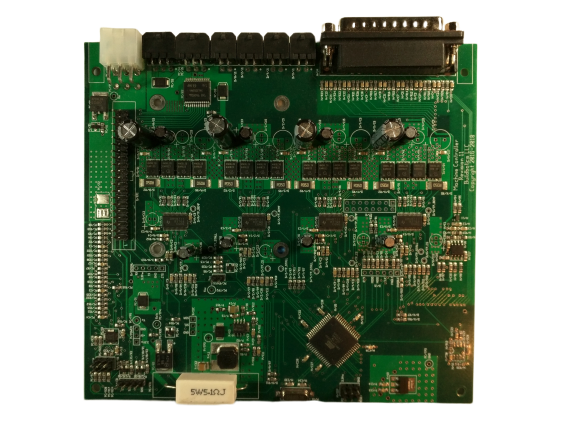
It works great with our latest hardware (V17) and latest software (V2.0.4). This table summarizes what you can expect with earlier versions of our hardware and software.
| Hardware | Software | Result |
|---|---|---|
| V17 or later | V2.0.4 or later | Excellent |
| ------------- | ---------------- | --------------------- |
| V17 or later | V2.0.3 or ealier | Good but limited |
| ------------- | ---------------- | --------------------- |
| V15 | V1.0.3 | Good but limited |
| ------------- | ---------------- | --------------------- |
| V14 or earlier | V1.0.3 | Good but limited and requires external hardware |
This article describes how to integrate the PwnCNC ATC system with a Buildbotics CNC Controller that has V17 or later hardware and V2.0.4 or later software.
Overview
The Buildbotics Controller connects to the PwnCNC Pneumatic Enclosure(PE) and the PwnCNC Variable Frequency Drive(VFD) through a DB25 breakout box that is connected to the back of the Controller.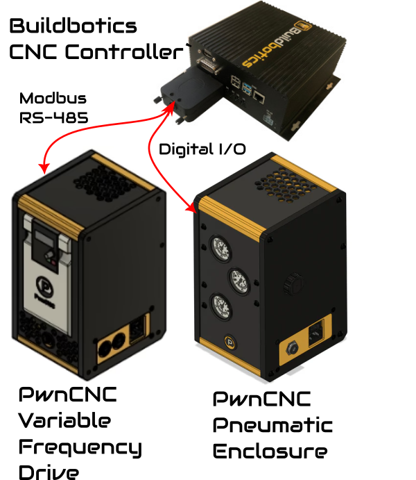
I recommend getting the ATC System running in manual mode first. Then, connect and configure the Buildbotics CNC Controller. The major steps are:
- Install the PwnCNC ATC System on your machine for manual operation.
- Connect the Buildbotics CNC Controller to the PwnCNC ATC System.
- Install the tool holders.
- Configure the Buildbotics CNC Controller.
Installing the ATC System for manual operation
Manual operation means that you can control the pneumatic chuck in the ATC spindle with a button. This makes tool changes much easier and faster, but still requires human intervention.
The PwnCNC ATC system comes with quite a few parts, and they describe them here.
PwnCNC describes how to get the system running in manual mode here.
Connect the Buildbotics CNC Controller to the PwnCNC ATC System
Both the VFD and PE connect to the BB Controller through a DB25 breakout box.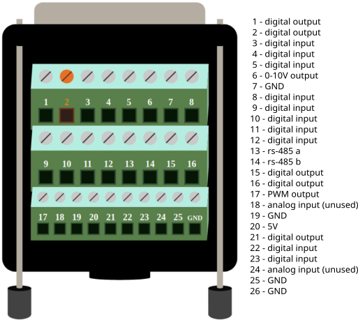
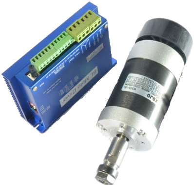
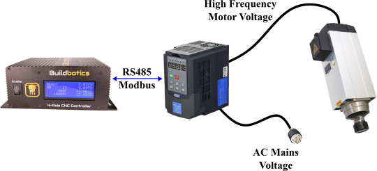
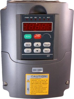
The BB Controller communicates with the VFD using a Modbus/RS-485 connection. The connector on the VFD is compatible with a 2-pin GX12 aviation plug.
Plug the modbus cable into the Modbus connector on the VFD. 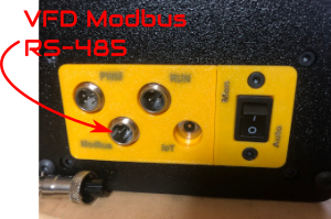
Connect pin 13 (rs485a) on the DB25 breakout box to pin 1 on the VFD Modbus connector and connect pin 14 (rs485b) to pin 2 on the VFD modbus connector.
Note, it is recommended that the two RS485 wires be twisted at about 1 turn per inch to reduce noise interference.
PwnCNC provided this control cable for connecting to the PE.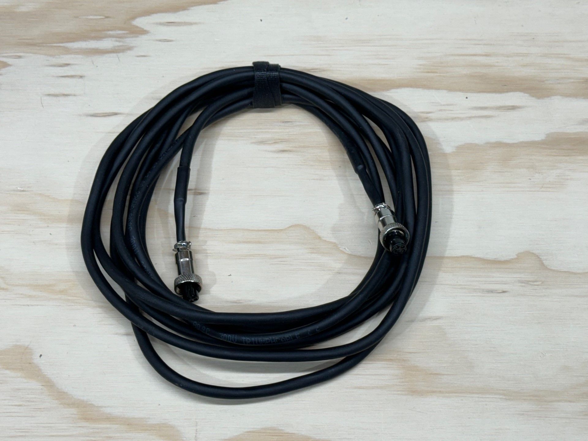
They also provided this cable for extending the control cable to a another controller.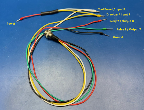
Plug the control cable into the Ctrl port on the PE and connect the extension cable to the control cable.
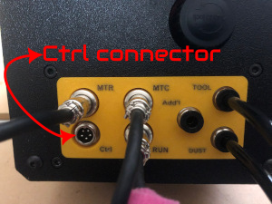
Connect the black wire (labeled Ground) from the extension to any of the ground wires on the DB25 breakout box. I chose pin 25.
The green wire (labeled Relay 1/Output 7) opens the air supply to the tool and dust outputs on the PE so a tool can be inserted. Connect the green wire to any unused digital output on the DB25 breakout box. I chose pin 15.
The red wire (labeled Relay 2/Output 8) opens the air supply to the addl output and can be used for other purposes. Connect the red wire to any unused digital output on the DB25 breakout box. I connected the red wire to pin 16 but am not using it in my system.
The extension has a yellow wire (labeled Drawbar/Input 7) that is connected to a red wire (labeled Power) This connection to power is not needed and you should cut the connection to the red (Power) wire, leaving the yellow wire intact.
Similarly, The extension has a white (labeled Tool Preset/Input 7) that is connected to a red wire (labeled power) This connection to power is not needed and you should cut the connection to the red (Power) wire, leaving the white wire intact.
Important! - The yellow and white wires from the PE present 24Volts DC when inactive and ground when active. If your Buildbotics Controller uses a board that is older than Version 15, a diode is required to protect the internal circuitry from the 24 Volt connection.
These connections are not absolutely required to make the ATC system and I recommend leaving them off for older Buildbotics Controllers. However, if you insist on connecting them, then connect low drop shottkey diodes (e.g. 1N4001) in line with the yellow and white wires to protect the circuits. The diode cathodes should point toward the PE.
If you don't know what version of main board your controller utilizes, you can contact Buildbotics at 707-559-8539 for that information.
You should also be aware that connecting the yellow or white wire to any pin other than a digital input will damage the Buildbotics Controller even if you have Version 15, or later, main boards.
Assuming your controller utilizes a Version 15 or later main board, then choose any unused digital input pin on the DB25 breakout board and connect the yellow wire to that pin. I chose pin 11 for the yellow wire.
Similarly, assuming your controller utilizes a Version 15 or later main board, then choose any unused digital input pin on the DB25 breakout board and connect the white wire to that pin. I chose pin 12 for the white wire.
Installing the tool holder
PwnCNC included four 3D printed tool holders with the system. I didn't want to drill holes in my table for this temporary installation, so I built this stand and screwed the 3D printed tool holders to the stand.
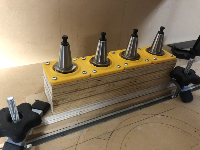
Then, I used workpiece hold-down clamps to hold it in place.
Configuring the Buildbotics Controller
With the system working in manual mode and all the connections intact, now is a good time to configure the Buildbotics Controller. To do this, we have to select the correct VFD, assign the digital I/O points, and tell the controller how to change tools, and how to park the last tool used at the end of a gcode program.
Selecting the VFD.
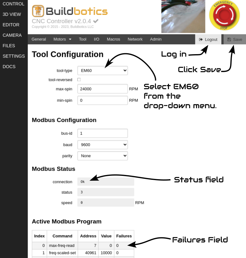
Use the following steps to select the PwnCNC VFD.
- Go to the SETTINGS->Tool page on the Buildbotics Controller.
- If the 'Login' button is green, click it and log in.
- Select 'EM60' from the 'tool-type' drop-down menu.
- Click the green 'Save' button.
If everything is working correctly, the Status field should say 'Ok' and the Failures field should not be increasing.
If the status field does not say OK or the Failures field is increasing try the following things.
- Verify that the VFD is turned on.
- Verify that the VFD is switched to 'Auto'.
- Verify that the connections to the 'Modbus' connector on VFD is properly seated.
- Verify that the pins 13 and 14 on the DB25 connector are securely connected.
- Verify that the DB25 breakout box is plugged into the back of the Buldbotics Controller and properly seated.
- Try reversing the connections between pin 13 and 14 on the DB25 breakout box.
- Call Buildbotics at 707-559-8539.
After the "Status' field says 'Ok' and the Failures field has stopped increasing, you can test the interface. Here's how:
- Navigate to the CONTROL page on the Buildbotics user interface.
- Select the 'MDI' tab.
- Enter M3S10000 and click play to turn the spindle clockwise at 10000 RPM.
- Enter M4 and click play to cause the spindle to stop and go in reverse at 10000 rpm
- Enter M5 to stop the spindle.
Configuring the digital I/O points
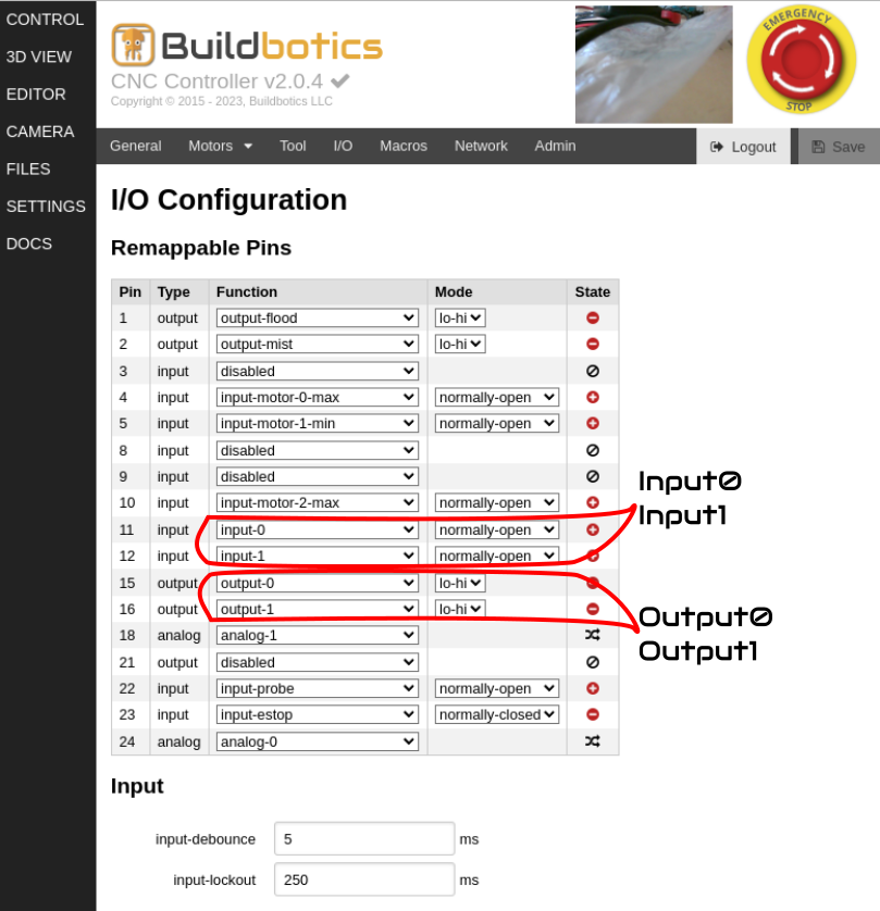
Follow these steps to configure the digital inputs:
- Navigate to the SETTINGS->I/O page.
- Find the pin that you connected to the yellow wire from the Ctrl extension cable. In my case, that is pin 11. Change the drop-down menu selection in the 'Function' column to 'input-0' and change the drop-down menu selection in the "Mode' column to 'normally-open'.
- Find the pin that you connected to the white wire from the Ctrl extension cable. In my case, that is pin 12. Change the drop-down menu selection in the 'Function' column to 'input-1' and change the drop-down menu selection in the "Mode' column to 'normally-open'.
- Click the green 'Save' button.
You can test this connection by using the manual tool change button to insert and remove a tool from the spindle chuck.
The icons next the the digital input pins will reflect the state of the input.
Input0 should momentarily flash from red to green when you insert or remove a tool from the spindle chuck.
Input1 should be green when a tool is in the chuck and red otherwise.
If the manual changes are working but the icons are not reflecting the correct state, check the wiring between the Buildbotics Controller and the PE.
Follow these steps to configure the digital output ports.
- Find the pin that you connected to the green wire from the PE Ctrl cable extension. Pin 15 in my case. Then,select 'output-0' from the drop-down menu in the 'Function' column and select 'lo-hi' from the drop-down menu in the 'Mode' field.
- Similarly, Find the pin that you connected to the red wire from the PE Ctrl cable extension. Pin 16 in my case. Then,select 'output-1' from the drop-down menu in the 'Function' column and select 'lo-hi' from the drop-down menu in the 'Mode' field.
- Click 'Save'
Use the following steps to test the digital outputs:
- Navigate to the CONTROL Page.
- Select the MDI tab.
- Enter 'M64 P0' and click play.
- You should now get non-zero readings on the tool and dust guages on the PE and air should be blowing in the spindle.
- Enter 'M65 P0' and click play.
- The tool and dust guages should go to zero.
- Enter 'M64 P1' and click play.
- The 'addl' guage should be non-zero.
- Enter 'M65 P1' guage should read zero again.
If the guages don't respond properly, try the following things:
- Verify that the PE is turned on.
- Verify that the air compressor is turned on and air is getting to the PE.
- Look at the icons next to pins 15 and 16 on the SETTINGS->I/O page to make sure they are changing state. If not, check the configuration.
- Check the wiring between the DB25 breakout box and the PE.
Telling the Buildbotics Controller how to change a tool
In order for the Buildbotics Controller to automatically change tools, it needs to know where each tool is located, how long the tools are, what to do when a tool change is requested, and how to park the last tool at the end of the program.
Locating your tool holders
Use the following procedure to locate your tools.
- Clear all offsets.
- Home your machine and do not set any offsets.
- Use the gamepad to jog your spingle to a height where it can move to any place on the table without running into anything. For me that height, which I'll call 'zSafe', is 200mm. Record the 'absolute' position of the Z axis.
- Use the gamepad to jog the spindle into a position directly above the tool location for your reference tool. You should center it perfectly over your tool holder. My reference tool is tool 1 and it is simply one of the ISO20 ER20 tool holders that was provided by PwnCNC with no tool. Since there is no tool, its length will be zero.
- Jog the Z axis to a position where it can safely drop the tool into the holder using the MTC button. Record the 'absolute' position of the Z axis. For me, that height is 43mm, which I'll call 'zDrop'.
- Jog the Z axis to a position where the you can pick up the tool from the tool holder using the MTC button. Record the 'absolute' position of the Z axis. For me, that height is 11mm, which I'll call 'zPick''.
- For each tool, find and record the 'absolute' positions for the X and Y axes.
Measuring the length of your tools
Use this program to measure the length of each tool:
%
M70
G21
M0 (MSG, insert the reference tool and attach the probe)
F100
G91
G38.2 Z-100
#31 = #5422
G0 Z50
M0 (MSG, insert tool to be measured)
G38.2 Z-100
#32 = [#5422 - #31]
G0 Z50
M0 (DEBUG, tool length is #32 mm)
M72
%
I recommend copying this code into a text file named something like 'measure_tool.ngc', uploading that file to the BB Controller and assigning it to a Macro button.
Run the program using the following steps:
- Put a reference tool in the chuck. (I use one of the ISO20 ER20 tool holders with no tool as a reference.)
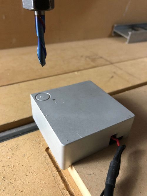
- Connect your height probe and place it on the CNC work surface.
- Jog the spindle into a place above your height probe.
- Click the tool measurement macro button.
- Connect the ground clip on the height probe to the reference tool.
- Wait for the controller to touch the probe and prompt you to put the tool to be measured in the chuck.
- Put the tool to be measured into the chuck.
- Click 'Continue'.
- Wait for the BB Controller to probe with the tool and display the length.
The length displayed will be the difference between the reference tool and the tool to be measured, which is the information needed for each tool.
You can see this in action on my Youtube video that demonstrates the use of this tool measurement program.
Also, check out my blog article titled CNC Macro Buttons to see how to create a macro button.
Telling the controller what to do when a tool change is requested
This program will reside in the 'tool-change' box on the SETTINGS->General page, and will be executed every time an 'M6TX' gcode command is encountered.
g4 p1
(Runs on M6, tool change)
M70
G21
#<_zSafe> = 200
#<_zDrop> = 43
#<_zPick> = 11

#<_zDust> = [#<_zPick> + 10]
#<_tool_table> = 2000 (store x location, y location, an tool length for each tool)

o<_make_tool> sub
  #[#<_tool_table> + [#1 * 3]] = #2 (x location)
  #[#<_tool_table> + [#1 * 3] + 1] = #3 (y location)
  #[#<_tool_table> + [#1 * 3] + 2] = #4 (z location)
o<_make_tool> endsub

(tool table is arguments to _make_tool call, arguments are:)
(tool number, x park position, y park position, tool length)
o<_make_tool> call [1] [-390] [-525] [0]
o<_make_tool> call [2] [-390] [-465] [46.2]
o<_make_tool> call [3] [-390] [-405] [32.8]
o<_make_tool> call [4] [-390] [-345] [27]

M66 P1 L0
o100 if [#<_x_homed> NE 1 or #<_y_homed> NE 1 or #<_z_homed> NE 1]
	(MSG, Error: System must be homed for ATC Operation)
	M2
o100 elseif [#5399 EQ 1 AND #5400 EQ -1]
    (DEBUG, Error: Unidentified tool is in the chuck #5400)
o100 elseif [#5400 NE #<_selected_tool>]
    #<xret> = #5420
    #<yret> = #5421
    M5 (stop the tool and wait five seconds)
    G4 P5
    o101 if [#5400 NE -1]
        (park the old tool)
        G53 G0 Z#<_zSafe>
        G53 G0 X#[#<_tool_table> + [3 * #5400]]Y#[#<_tool_table> + [3 * #5400] + 1]
        G53 G0 Z#<_zDrop>
        M64 P0
        G4 P2
        M65 P0
        G53 G0 Z#<_zSafe>
        #<new_offset> = [#5213 - #[#<_tool_table> + [3 * #5400] + 2]]
        G92 z[#<_zSafe> - #<new_offset>]
    o101 endif
    (get the new tool)
    #<t> = #<_selected_tool>
    G53 G0 Z#<_zSafe>
    G53 G0 X#[#<_tool_table> + [3 * #<t>]]Y#[#<_tool_table> + [3 * #<t>] + 1]
    G53 G0 Z#<_zDust>
    M64 P0
    F300
    G53 G1 Z#<_zPick>
    M65 P0
    G4 P2
    G53 G0 Z#<_zSafe>
    #<new_offset> = [#5213 + #[#<_tool_table> + [3 * #<_selected_tool>] + 2]]
    G92 z[#<_zSafe> - #<new_offset>]
    G0 X#<xret> Y#<yret>
o100 endif

M6
M72
Use the following steps to modify this file with the values, tool numbers, tool locations, and tool lengths from previous steps.
- Copy the program into a text editor so you can easily edit it.
- Change the value for zSafe on line 5 to the value you recorded for zSafe.
- Change the value for zDrop on line 6 to the value you recorded for zDrop.
- Change the value for zPick on line 7 to the value you recorded for zPick.
- For each tool starting at line 20, modify the arguments with the tool number, x location, y location and tool length. For instance the second line (line 21 in the program) for my system shows that tool 2 is located at -390mm on the X axis, -465mm on the Y axis, and has a relative length of 46.2mm.
- Copy all the contents of the file and paste them into the 'tool-change' textbox on the SETTINGS->General page and then click 'Save'.
Parking the tool at the end of the program
I like to park the tool and move the spindle to a convenient place at the end of a gcode program because:
- The last tool used by a program is retained by the system. However, if the controller is turned off, it loses this information. Then, if you try to run a program after turning the controller back on and the previous tool is still in the chuck, it could cause a crash. Parking the last tool at the end of the program and setting the tool to '0' avoids this problem.
- I like to move the spindle to a position near my limit switches. This way, when I turn the controller off and back on, homing is much faster because the spindle is already close to it's home position. For me that position is Z=175, X=380, Y= -550.
The following program drops the last tool used by the program into its tool holder and parks the spindle near the homing limit switches.
(Runs on M2, program end)
M70
G21
o200 if [#5400 GT 0]
    M5 (stop the spindle and wait 5 seconds)
    G4 P5
    (park the old tool)
    G53 G0 Z#<_zSafe>
    G53 G0 X#[#<_tool_table> + [3 * #5400]]Y#[#<_tool_table> + [3 * #5400] + 1]
    G53 G0 Z#<_zDrop>
    M64 P0
    G4 P2
    M65 P0
    G53 G0 Z#<_zSafe>
    #<new_offset> = [#5213 - #[#<_tool_table> + [3 * #5400] + 2]]
    G92 z[#<_zSafe> - #<new_offset>]
o200 endif
M6T0
#5400 = -1
(park near the limit switches)
G53 G0 Z175
G53 G0 X380 Y-550
M72
M2
Use the following steps to modify this program with your preferred park position and load it into your Buildbotics Controller.
- Copy the program into a text editor so you can easily edit it.
- Change the Z value on line 20 to your preferred Z axis park position.
- Change the X and Y values on line 21 to your preferred X axis and Y axis park positions.
- Copy and paste it into the 'program-end' textbox on the SETTINGS->General page and then click 'Save'.
Relavant links
Check out my video titled Integrating the PwnCNC Automatic Tool Changer with the Buildbotics Controller to see the system actually doing a cut.
Also check out my video titled Measuring tools for an Automatic Tool Changer using a macro button on a Buildbotics Controller to see the tool measurement macro in action.
Finally, check out my blog article titled CNC Macro Buttons to see how to create a macro button.
