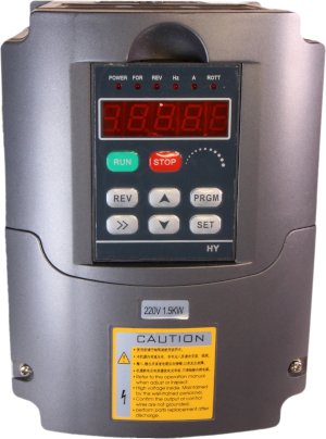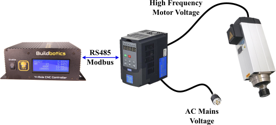
A VFD or Variable Frequency Drive is a type of motor driver often used to control high speed CNC spindles. The VFD converts AC line voltage to higher voltages and frequencies. The VFD varies the output frequency to control motor speed. Using a VFD smart controller, like the Buildbotics CNC controller, you can control spindle speed and direction using GCode and get feedback indicating actual speed in real-time.
You may also be interested in PWM spindle control.
RS485 VFD Control
Most VFDs support remote control using the two wire RS485 digital interface. This allows a smart CNC controller to command the VFD's speed and direction and read back actual speed and status information while the VFD is running. Most also use a protocol called Modbus when communicating over RS485. Unfortunately, compatibility ends here because each VFD vendor uses a different set of Modbus commands.
Fortunately, the Buildbotics CNC controller has built-in configurations to handle many common VFDs and makes it possible to create custom configurations to support new ones.
Supported VFDs
Any VFD that supports Modbus can be used with the Buildbotics controller. However, some VFDs have out-of-the-box support and others require custom programming. At the time of this writing the following VFDs are supported out-of-the-box:
- Huanyang
- AC-Tech
- Nowforever
- Delta VFD015M21A (Beta)
- YL600, YL620, YL620-A (Beta)
- FR-D700 (Beta)
VFDs marked as beta have had limited testing. If you need help with one of these VFDs or would like to create a custom configuration for a new VFD, don't hesitate to contact us. We will be glad to help decipher the VFD's manual and are eager to add support for more VFDs.
RS485 Wiring
Only two wires are needed to make the RS485 connection. To reduce electrical noise it is best to keep the wires short and to use a shielded twisted pair such as one of the pairs found in a CAT5 network cable.
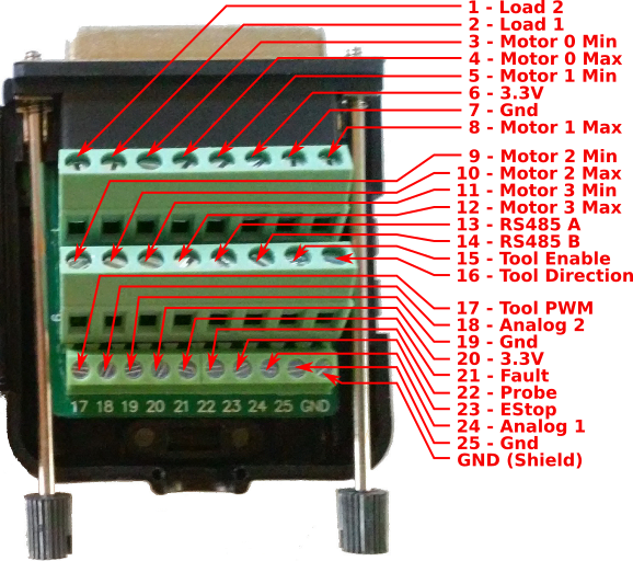
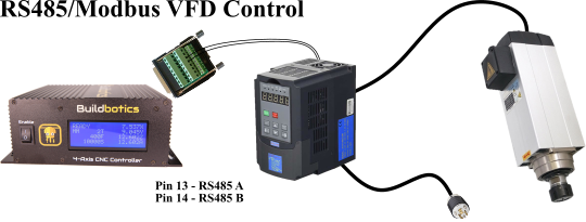
First, disconnect all power. Then, make the following connections on the Buildbotics controller I/O breakout box.
| Pin | Signal |
|---|---|
| 13 | RS485 A |
| 14 | RS485 B |
You can connect either wire to RS485 A or B; the Buildbotics controller will automatically discover which is which. Consult the VFD's manual for the correct connection points on the VFD. Be sure not to connect the RS485 wires to any of the high voltage lines with in the VFD.
Buildbotics Controller Configuration
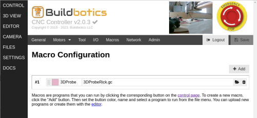
To configure the Buildbotics controller to talk to the VFD go to the TOOL page on the Web interface and configure the following sections:
Tool Configuration
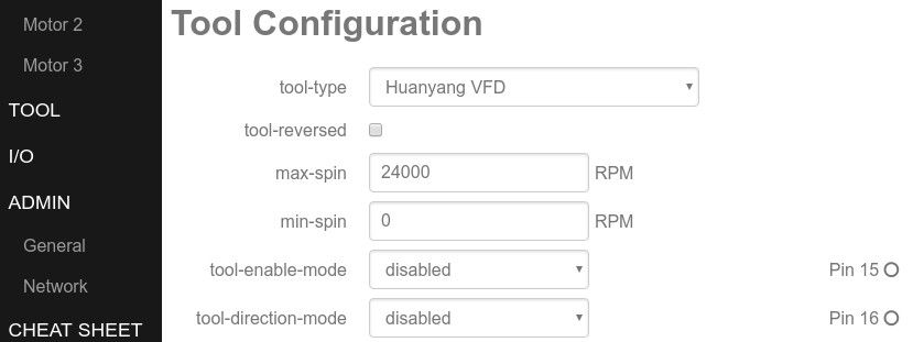
tool-type
Select one of the built-in VFD configurations or "Custom Modbus VFD" to design your own VFD control commands.
tool-reversed
Check this box if your spindle turns the wrong direction. Most tools require clockwise rotation. That is clockwise if you are looking down from above the spindle towards the workpiece. Spinning the tool in the wrong direction can cause major problems so double check it before you cut anything.
max-spin & min-spin
Maximum and minimum spindle speed in RPM (Revolutions per Minute). Check your VFD's manual to determine the correct values for your spindle. A typical maximum RPM is 10k to 24k.
tool-enable-mode & tool-direction-mode
These options are not normally needed for RS485 VFD control. Set them disabled.
Modbus Configuration
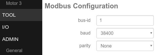
There are a number of configuration options on the Buildbotics controller that are common to all VFDs. These options must match the settings applied in the VFD's configuration.
bus-id
This is the Modbus ID. It is used to identify multiple Modbus devices on the same RS485 network. Typically there is only one device so bus ID 1 is a good choice. It just has to match the setting in the VFD.
baud
This is the speed of the RS485 communication in bits per second. It is tempting to use higher baud rates but this only increases the likelihood of errors due electrical noise. The spindle control signals are very brief and even at 9600 baud it is already very fast. For example, a typical command and response consists of 176 bits of data. At 9600 baud that takes about 1/50th of a second.
parity
The parity bit is an extra bit that is used to help detect communication errors. The Modbus protocol already has it's own error checking so parity is generally set to none. However, it must match the setting in the VFD.
Configuring the VFD
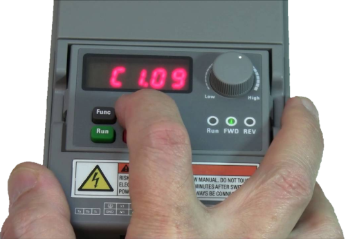
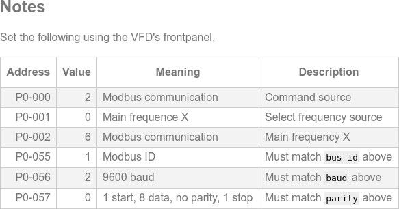
You must configure the VFD for your spindle and enable Modbus communication. If you select one of the preconfigured VFDs, a "Notes" section will appear at the bottom of the page showing the necessary VFD settings.
The configuration process varies for each VFD so consult its manual for details. It usually consists of using the arrow and enter keys on the VFD's front panel to select an address and then set its value. This is repeated for each setting until all the necessary settings are configured.
Here are the most common VFD settings needed for Modbus communication:
- Enable RS485 Modbus communication in RTU mode.
- Select 9600 baud.
- Select no parity, 8 data bits and 2 stop bits.
- Set the Modbus slave ID to 1 or whatever you set bus-id to.
- Select Modbus as the start/stop controller and remote frequency source.
You will also need to set the correct frequency, output voltage and min and max RPM for your spindle in the VFD's configuration.
Testing the Connection
With the RS485 wiring complete and the Buildbotics controller and VFD configured, it's time to test the connection. Test with the spindle disconnected from the VFD until you're sure the VFD is operating correctly.
To start the VFD in the clockwise direction go to the CONTROL page on the Buildbotics controller, select the "MDI" tab, then run the following GCode command:
M3 S1000
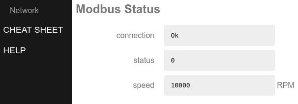
Return the the TOOL page to check the Modbus status. The VFD's front panel may also indicate if it is operating.
Increase the speed with:
S5000
Reverse the direction with:
M4
Stop the VFD by clicking the stop button or with:
M5
Once everything appears to be working correctly, disconnect the power, connect the spindle, power it up and try it again for real. Be sure to check that the spindle turns in the correct direction.
Troubleshooting
VFD fails to operate
Check the following:
- Both RS485 wires are solidly connected to both the Buildbotics controller and the correct connection points on the VFD.
- The following settings match on both the Buildbotics controller and VFD:
- Modbus ID
- RS485 baud rate
- RS485 data bits, parity and stop bits
- The VFD is in Modbus RTU mode. Not ASCII mode.
- RS485 Modbus is the source for start/stop and frequency control on the VFD.
- The VFD can be operated manually through its front panel.
Spindle runs in reverse
If an M3 causes the spindle to turn counter-clockwise you can either correct the configuration in the VFD or set the tool-reversed option on the Buildbotics controller.
Spindle runs at wrong speed
Check that:
- max-spin is correct on the Buildbotics controller.
- The maximum frequency is set correctly on the VFD.
- The VFD program uses either max-freq-read or max-freq-fixed to get the VFD maximum frequency.
- Make sure the VFD output frequency is correct for your spindle motor.
Spindle does not turn a low speeds
Many VFDs will not turn or have very weak torque below a certain speed.
Creating a Custom VFD Program
If there are no preexisting configurations for your VFD but you have the VFD's manual or datasheet, it's time to create a custom VFD control program. For testing a new VFD program, the VFD must be powered on but you should not connect the spindle until the program appears to be correct. Incorrect programming could permanently damage your VFD or spindle. Read the VFD manual carefully!
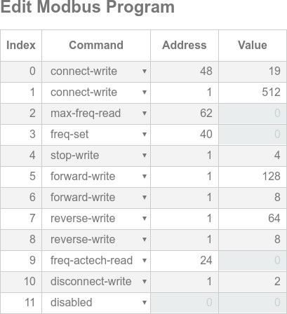
On the TOOL���� configuration page set tool-type to "Custom Modbus VFD". Then scroll down and begin adding VFD commands. To add a new VFD command:
- Select the command type using the drop down menu.
- Set the address specified in the VFD's manual.
- For write operations, set the value according the the manual.
Modbus Addresses
The manual may show the addresses or values in hexadecimal so be sure to convert to decimal.
Sometimes the Modbus addresses appear in two parts. For example: P01.05. Usually, this corresponds to a high and low byte. In this case the address in decimal is computed as:
address = high_byte x 256 + low_byte
So for P01.05 we have:
1 x 256 + 5 = 261
Modbus Control Flow
Modbus commands are executed according to the above state diagram. Repeated commands are executed in the order they appear. Click the green "Save" button for the commands to take affect.
Monitor the Modbus status and Active Modbus Configuration failures to see how the program progresses. If you see failures counting up on a command that means it is failing. The Modbus control flow is restarted after any failure. If the very first command fails it may indicate that the communication settings don't match the VFD or the RS485 connection is wired incorrectly.
Modbus Commands
The following table defines all of the Modbus commands used to create VFD configurations with the Buildbotics controller:
| Name | Type |
|---|---|
| connect-write | write |
| max-freq-read | read |
| max-freq-fixed | constant |
| max-freq-read | read |
| freq-set | write |
| freq-signed-set | write |
| stop-write | write |
| forward-write | write |
| reverse-write | write |
| freq-read | read |
| freq-signed-read | read |
| freq-actech-read | read |
| status-read | read |
| disconnect-write | write |
Write commands write their value to the specified address. Read commands read from the specified address and do not require a value. Constant commands do not require an address but do require a value.
connect-write
These commands are executed once whenever the Buildbotics controller connects to the VFD. connect-write commands are used to perform any necessary initialization. You can enter more than one connect-write command or none at all. They will be executed in order.
max-freq-read & max-freq-fixed
Get the maximum frequency used by the VFD. Rather than report speed, VFDs usually report the current frequency. The Buildbotics controller needs the maximum frequency to calculate the speed.
max-freq-read reads the maximum frequency from a register in the VFD as an unsigned 16-bit integer. max-freq-fixed does not actually query the VFD but sets a fixed value for the maximum frequency. It must match the value programmed in the VFD.
freq-set & freq-signed-set
Set the VFD's target frequency and indirectly the spindle speed. Use freq-set for VFDs that used an unsigned frequency and a separate direction setting. freq-signed-set is for VFDs which equate negative frequencies with reverse spin.
stop-write, forward-write & reverse-write
Stop the spindle or command it to spin forward or in reverse. These commands are not always required. Some VFDs use a frequency of zero for stop, positive frequency for forward and negative for reverse.
freq-read, freq-signed-read & freq-actech-read
While the VFD is running the Buildbotics controller will repeatedly read the VFD's output frequency to determine the actual spindle speed. Most VFDs use freq-read to read an unsigned 16-bit integer value, a few use freq-signed-read to read a signed 16-bit integer and ACTech VFDs use freq-actech-read to do a special multi-read.
In order to compute the spindle's actual speed, max-rpm must be set correctly and either max-freq-read or max-freq-fixed must be used to get or set the maximum frequency. Spindle speed is calculated as:
speed = frequency / max-frequency * max-rpm
status-read
Some VFDs require regular communication to keep the connection from timing out and the VFD from automatically turning itself off. The status-read command can be used as a heartbeat signal. The returned value is recorded and reported on the TOOL page and in the "indicators" tab on the CONTROL page but is otherwise unused.
disconnect-write
It is not usually necessary but if there are any commands that need to be run before the VFD is disabled they can be entered as disconnect-write commands.
Sharing A New Custom VFD Program
If you have successfully created a new VFD program or need help with one you're working on, email us your controller configuration file using the following procedure:
- Click the "Save" button in the Buildbotics controller's Web interface.
- On the ADMIN page click "Backup" under the "Configuration" heading.
- Download the configuration file to your computer.
- Attach the configuration file to an email.