CNC machines 'probe' to find the workpiece and then set the Offsets accordingly. Probing is controlled using G-Code commands on the Buildbotics CNC Controller.
The most common use of probing is to adjust the offset for the z-axis after a bit is changed. This allows changing bits during the execution of a single GCode program.
This article describes how to use probing on a Buildbotics CNC Controller but the concepts are also applicable to most other controllers.
Also, check out my video on 3D Probing.
What is a CNC probe?
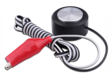
A probe is a simple device that provides a state change on a pair of wires when it comes in contact with the bit on your CNC machine. All you really need is a metal plate with a known height that has two wires connected. I use one like the one shown below, but it wouldn't be hard to make your own. These probes are readily available for just a few dollars.
How to connect the probe to your controller
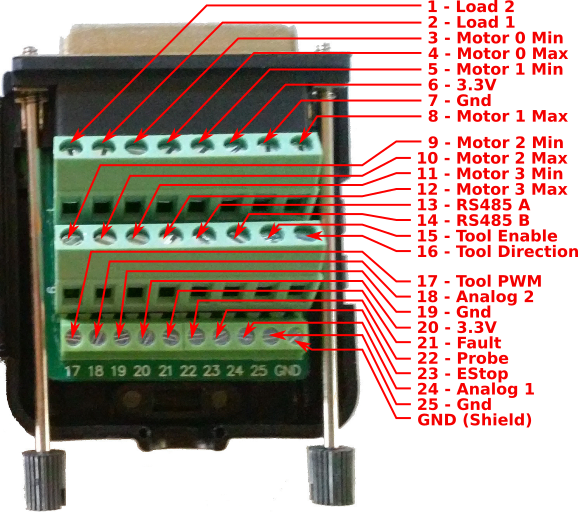
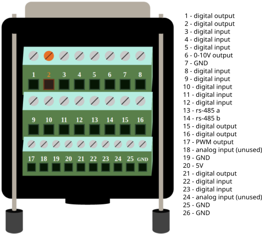
Simply connect the wire that attaches to the metal plate to one of the digital inputs on the Buildbotics Controller and connect the other wire to one of the ground leads on the Buildbotics Controller. Both connections are made through the DB25 breakout box that comes with the controller.
How to configure the probe.
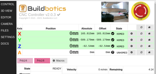
Go to the SETTINGS->I/O page to configure the input pin that you selected for the probe. Pin 22 is used in the image below. Set the function for the pin to 'input-probe'. Then, set the Mode to 'normally-open'. Click the green 'Save' button to save your work.
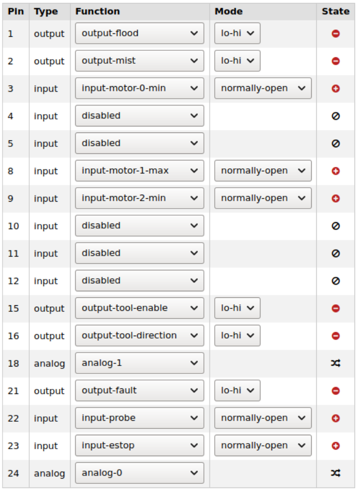
The icons in the State column report the current state of the input and are really handy for troubleshooting your probe and connections.
- If the icon is green with a '-' sign, the probe plate is touching the ground connection.
- If the icon is red with a '+' sign, probe plate is not touching the ground connection.
How to use it
The probe provides a known height that allows you to determine height of the tip of the bit. For instance, my probe plate is 3/4" (19.05mm) tall. If the bit is just touching the probe plate then it is 19.05 mm above the top surface of the workpiece. I always set up my GCode designs so that the top surface of the workpiece is set to 0. So, all I have to do is set the height to 19.05mm when the probe touches the workpiece.
Start by connecting the probe to the controller, placing the probe plate on the top surface of the workpiece, and moving the tool to a place just above the probe plate.
Issue the following GCode commands to use metric units and set the speed at which the tool will approach the probe.
G21 (use metric units)
F100 (sets the feed rate to 100 mm/minute)
Then, issue the following command to tell the controller to move down towards the probe and stop when contact is made or fail if it moves down by 100mm without making contact.
G38.2 Z-100
Then, use the following command to set the Z-axis position to 19.05mm.
G92 Z19.05
You can do these commands manually with from the MDI interface on the CONTROL page on the Buildbotics Controller, or you could put these commands into a Macro button.
Automating the process
Lumping the GCode commands into a macro provides some convenience, but it still does not allow you to change bits while running a GCode program. You could issue the commands from within the GCode program, but the Buildbotics Controller provides a better way.
You can configure the Buildbotics Controller to automatically issue a block of commands every time a tool change is encountered. Simply enter the required commands into the 'tool-change' text box on the SETTINGS->General page.
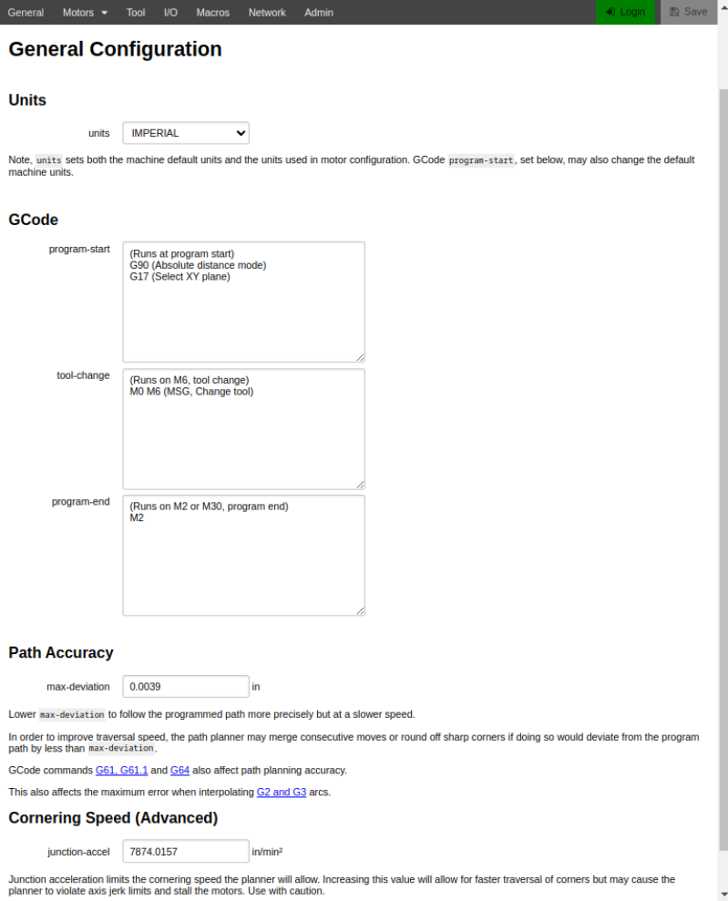
The following commands can be cut and pasted into the 'tool-change' text box and will handle most of your z-axis probing needs.
M70 (save the current machine state. (e.g. feed rate and units)
G21 (metric units)
G90 (set the machine to "absolute distance mode")
G0Z50 (raise the spindle to a height that makes it easy to change the bit)
G0 X-50Y-50 (make a rapid move to a good place to sit the probe plate)
M0 (MSG, Change bit and attach probe) (prompt the user to change the bit and attach the probe)
G91 (put the machine in "incremental distance mode")
F100 (set the feed rate to a slow speed for probing)
G38.2 Z-100 (probe down until the plate is touched or until Z has moved by -100mm)
G92 Z19.05 (set the Z axis to the height of the probe plate)
G90 (set the machine to "absolute distance mode")
G0 Z50 (raise the Z axis to a safe height where it is easy to remove the probe.)
M0 (MSG, Remove the probe) (prompt the user to remove the probe)
M72 (recover the original machine state(e.g. feed rate, distance mode, and units))
You can learn exactly how each of these commands work from the LinuxCNC GCode Documentation.
3D Probing
The Buildbotics Controller can probe on any or all four of its axes. 3D Probing is commonly used to find the corner of a workpiece and set the offsets on the X, Y, and Z axes from the result.
The following block of GCode will find the front, top, left corner of your workpiece and set the position to X=0, Y=0, Z=0. It works very much like the z-axis probing code but extends the same concepts to all three axes.
This program makes use of 'named parameters'.
(to use this program, simple place the probe plate on the front, left corner of the workpiece)
( and move the bit over the circle at about 1" above the plate, then run the program)

(All dimensions should be entered in millimeters)

#<_x_outer_dim> = 63.18 (Change to the outer size of the probe plate in the x direction)
#<_x_inner_dim> = 53.92 (Change to the size of the inset part probe plate in the x direction)
#<_y_outer_dim> = 63.28 (Change to the outer size of the probe plate in the y direction)
#<_y_inner_dim> = 54.34 (Change to the size of the inset part probe plate in the y direction)
#<_height> = 18.88 (change to the overall height of the probe plate)
#<_inset_height> = 14.9 (change to the height of the inset part of the probe plate)
#<_circle_x> = 10 (change to the approximate circle x position on the probe plate)
#<_circle_y> = 10 (change to the approximate circle y position on the probe plate)

M70 (push state)
G21 (Change to metric units)
M5 (stop the spindle)

(prompt the user to attach probe and confirm that it is over the circle)
M0 (MSG, Attach probe and confirm that the center of the bit is over the circle)

G92 X0Y0Z0 (set all offset positions to 0)
F100 (set the feed rate to 100 mm/min)

(the next set of commands determine z height)
G38.2 G91 Z-100 (probe z by as much as 100 mm)
G92 Z[#<_inset_height>] (set z-axis to the height of the probe)

(the next set of commands determine the radius of the bit)
G0 G90 Z[#<_inset_height> + 10] (raise z to 10 mm above the top of the probe plate)
G0 G91 X[#<_x_outer_dim> - #<_circle_x> + 20] (rapid x to approximately 20mm past the right side of the probe)
G1 G90 Z[#<_inset_height> - 5] (move to 5mm below the top surface of the probe plate)
M0 (MSG, align flute for x probe)
G38.2 G91 X-25 (probe by up to 25mm to the left to find the right edge of the probe plate)
#<_right_side> = [#<_x>]
G0 G91 X1 (back off by one mm)
G0 G90 Z[#<_inset_height> + 10] (rapid to safe height)
G0 G91 X[-1 - #<_x_outer_dim> - 20] (rapid to the 20 mm past the left edge of the probe plate)
G1 G90 Z[#<_inset_height> - 5] (move to 5mm below the top surface of the probe plate)
M0 (MSG, align flutes for x probe)
G38.2 G91 X25 (probe by up to 25mm to the right to find the for left edge of the probe plate)
#<_left_side> = [#<_x>]
#<_diameter> = [#<_right_side> - #<_left_side> - #<_x_outer_dim>]
#<_radius> = [#<_diameter> / 2]

(now set the x postion to be 0 - 'x outer dimension - x inner dimension' - radius)
G92 X[0 - #<_x_outer_dim> + #<_x_inner_dim> - #<_radius>]

(next set of commands probe y and set y position)
G0 G91 X-1 (back away by one mm)
G0 G90 Z[#<_inset_height> + 10] (rapid to safe height)
G0 G91 X[1 + #<_radius> + #<_circle_x>] Y[-#<_circle_y> - 20] (rapid to the circle x pos and 20 mm below the lower y edge)
G1 G90 Z[#<_inset_height> - 5] (move to 5mm below the top surface of the probe plate)
M0 (MSG, align flutes on [#<_radius>] bit for y probe)
G38.2 G91 Y25 (probe by up to 25mm to back to find the front edge of the probe plate)

(now set the y postion to be 0 - 'y outer dimension - y inner dimension' - radius)
G92 Y[0 - #<_y_outer_dim> + #<_y_inner_dim> - #<_radius>]
G0 G91 Y-1 ( back away by one mm)
G0 G90 Z[#<_inset_height> + 10] (rapid to safe height)
G0 X0 Y0(move to the front left corner of the workpiece)
M0 (MSG, Remove probe)
M72
You should measure the dimensions of your 3D probe and replace the dimensions at the top of the program with your actual dimensions.
Normally, you would not run a 3D probe sequence after every tool change, but you may want to enter this code into the 'start-block' on the SETTINGS->General page. The 'start-block' gets executed at the beginning of each GCode program.
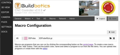
You may also find it helpful to add the 3D probing sequence to a Macro button.
Summary
- Probing provides an automated and repeatable method of setting CNC Offsets.
- Probing enables the use of multiple bits in a single CNC Program.
- Probing is mostly used to set the offset for the z-axis, but it can also be used to set offsets for all axes.
- The Buildbotics Controller implements probing through GCode commands, which means it can easily be performed as a 'code block' that is triggered when a tool change is encountered in the program.
Take a look a my article on Macros where I assigned the 3D probing sequence to a macro button.
Todo
Add link to Macro button article