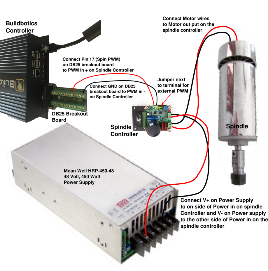
- Connect Pin 17 (spin pwm) the DB25 Breakout Board to the PWM+ input on the Spindle Controller.
- Connect GND on the DB25 Breakout Board to PWM- on the Spindle Controller.
- Move the jumper on the Spindle Controller to the "J21" position.
- Connect the red wire from the Spindle to M+Load terminal on the Spindle Controller.
- Connect the black wire on the Spindle to the M-Load terminal on the Spindle Controller.
- Connect a V- terminal on the 48VDC power supply to the Power-In side of the AC/DC connector on the Spindle Controller.
- Connect a V+ terminal on the 48VDC power supply to the positive side of the AC/DC connector on the Spindle Controller.
- Connect the DB25 Breakout Board to the back of the Buildbotics Controller.
- Connect power to the 48VDC power supply.
- Connect the 24-48VDC power supply to the Buildbotics Controller and turn it on.

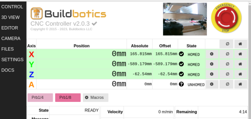
After the Buildbotics Controller boots, navigate to the "Tool Configuration" page and set the following parameters.
- Set 'tool-type' to 'PWM Spindle'.
- Leave 'tool-reversed' unchecked. (If the spindle turns backwards, either check this field or reverse the wires between the Spindle and the Spindle Controller.
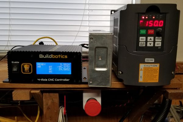
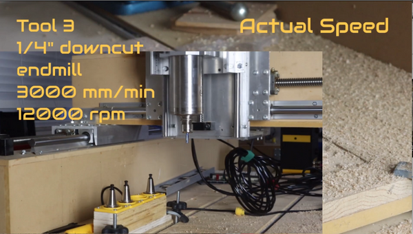
- Set 'max-spin' to 12000 RPM. This value varies with the type of spindle and controller, but the common spindle and controller shown should be set to 12000.
- Set 'min-spin' to 0.
- Set 'tool-enable-mode' to 'lo-hi'.
- Set 'tool-direction-mode' to 'disabled'. The Spindle Controller shown does not provide reverse operation. If your Spindle and Spindle Controller do support reverse operation, connect the wire to pin 16 and set this field to the value needed for the spindle controller.
- Leave 'pwm-inverted' unchecked.
- Set 'pwm-min-duty' to 1
- Set 'pwm-max-duty' to 100
- Set 'pwm-freq' to 1000
- Leave 'rapid-auto-off' and 'dynamic-power' unchecked. These fields are mostly used for laser engravers.