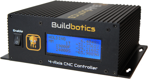
The Buildbotics CNC Controller provides four bipolar stepper motor drivers. It cannot drive unipolar stepper motors. Fortunately, most stepper motors can be wired up as bipolar motors.
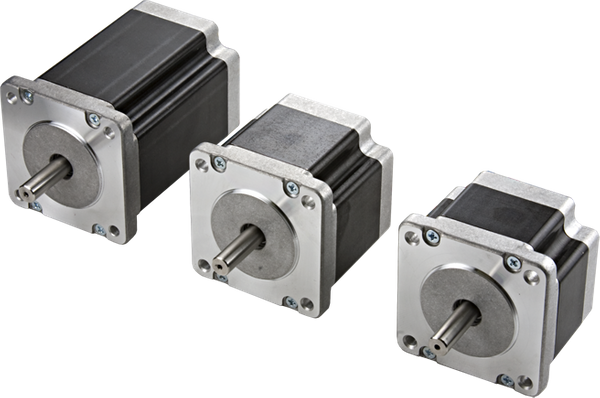
Connecting a stepper motor to a Buildbotics CNC Controller requires properly connecting the four wires from the driver to the right wires on the motor. Unfortunately, stepper motors come in a variety of configurations and it is not always immediately obvious how to hook them up. There are several characteristics that make stepper motors different from one another. One big difference is the number of wires emanating from the motor. It is not uncommon to encounter motors with 4, 5, 6, or 8 wires coming out of the motor. This article discusses each of those configurations.
The Buildbotics CNC Controller provides four motor driver outputs through the back panel on ports labeled X, Y, Z, and A. All four of these ports are wired the same and they look like this:
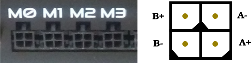
Each output has four pins. The upper left pin is B+, the lower left is B-, the upper right is A-, and the lower right is A+. B- and B+ must drive one of the motor coils and A- and A+ must drive the other motor coil.
Buildbotics provides pre-made cables that connect to the driver outputs on one end. These cables are color coded such that the A+ wire is red, the A- wire is black, the B+ wire is yellow, and the B- wire is purple.
Connecting 4-wire motors
Connecting 4-wire stepper motors requires connecting A+ and A- to one of the motor coils and B+ and B- to the other motor coil.

The trick is figuring out which wires make up the coil pairs. Here’s three ways to figure this out:
- Find the documentation for the motor. Assuming you don’t already have it, read the model number off of the motor and then search for it on the Internet. With a little effort, it is usually possible to get a datasheet for the motor. The datasheet will usually specify the wires by A+, A-, B+, and B-, or at least show which wires by color attach to which coils.
- If you can’t find the datasheet, but have an ohmmeter, measure the resistance between any two of the motor wires. If you measure a near short, then that pair makes up one coil, and the other two wires make up the other coil. If it is an open, then measure between the first wire and another wire and then to the fourth wire until you find a near short. Notice that I say near short because the coil is a long thin wire and has some resistance. Once the pairs are identified, then arbitrarily assign one pair as “A” and the other as “B” and arbitrarily assign one wire as “+” and the other as “-” within each pair. Then connect the wires as shown. There is a 50% chance that the motor will turn backwards when connecting this way. If it does turn the wrong way simply reverse one (not both) of the pairs and the motor will turn the other direction.
- If you don’t have an ohmmeter, most people can identify the pairs by feel. Stepper motor shafts turn fairly easily when the motor coils are open, but are more difficult to turn when a coil is shorted. First, leave all four motor coils open and turn the motor shaft to get a feel for how hard it is to turn. Then twist any two wires together. If the motor is significantly harder to turn, then you have shorted one of the coils and identified a pair. If not, disconnect the two wires from each other and connect a third wire to the first wire. If the motor doesn’t get harder to turn, disconnect the third wire from the first wire and connect the fourth wire. One of the combinations should be harder to turn and that is one coil and the two wires make up the other coil. Once the pairs are identified, then arbitrarily assign one pair as “A” and the other as “B” and arbitrarily assign one wire as “+” and the other as “-” within each pair. Then connect the wires as shown. There is a 50% chance that the motor will turn backwards when connecting this way. If it does turn the wrong way simply reverse one (not both) of the pairs and the motor will turn the other direction.
Connecting 5-wire motors
5-Wire motors are strictly unipolar motors and cannot be wired as bipolar motors. As such, they are not compatible with the Buildbotics CNC Controller.
Connecting 6-wire motors
6-wire motors can be configured as either unipolar or bipolar series motors. The Buildbotics CNC Controller does not support unipolar motors. The bipolar series connections are shown here.

6-wire motors have two center-tapped coils and expose the ends of the coils and the center tapped conductor of the coil. That’s three wires for each of the two coils. The center taps are not connected and the coil ends are connected as shown. The trick is figuring out which wires belong to each coil and which of those wires are the center conductor. Here are two methods:
- Find the documentation for the motor. Assuming you don’t already have it, read the model number off of the motor and then search for it on the Internet. You may have to call the vendor. With a little effort, it is usually possible to get a datasheet for the motor. The datasheet will usually specify the wires by A+, A-, B+, and B-, or at least show which wires by color attach to which coils.
- Use an ohmmeter to identify the individual coils. Any wires that appear to be connected through a few ohms will be part of one coil. Wires that appear to be open are part of the different coils. Arbitrarily choose one of the coils as “A” and the other as “B”. Once the coils have been identified, measure the resistance between each of the three wires on that coil. The resistance between the two coil ends will appear to be about twice the resistance between the either coil end and the coil center tap. When the coil ends have been identified, arbitrarily choose one of the ends to be “+” and the other to be “-” for each coil. Then connect the wires as shown. There is a 50% chance that the motor will turn backwards when connecting this way. If it does turn the wrong way simply reverse one (not both) of the pairs and the motor will turn the other direction.
Connecting 8-wire motors
Eight wire motors can be configured as unipolar, bipolar series, or bipolar parallel motors. The Buildbotics CNC Controller does not support unipolar connections. Before configuring an 8 wire motor, you must first decide whether to configure the motor as a bipolar series or a bipolar parallel motor. Bipolar parallel connected motors will generally provide higher top speed, but will require twice as much current as a series connected motor. A series configuration should be used if the parallel configuration current exceeds the output capability of the driver. This is especially true for larger motors. In the case of the Buildbotics CNC Controller the maximum current is 6 amps for any individual motor port.
The following diagram shows the connections to be made for an 8-wire series connected bipolar stepper motor.

The next diagram shows the connections for an 8-wire parallel connected bipolar stepper motor.

It is not realistic to sort out all of the possible combinations of connections with an ohmmeter or by feel. You need the datasheet for the motor to hook it up. Assuming you don’t already have it, read the model number off of the motor and then search for it on the Internet. You may have to contact the vendor to get the motor datasheet. The datasheet will usually specify the wires by A1+, A1-, A2+, A2-, B1+, B1-, B2+, and B2-, or something like that. Given that information, simply wire the motors as shown in the diagrams above.