Over the last two years, Doug Coffland and I have been developing the Buildbotics Open-Source CNC Controller. We had to overcome many hurdles before we could launch this product. This article is a deep dive into how we hacked the DMA controller of an 8-bit ATXMega to produce steps rates in excess of 250k/sec on four separate motor channels while also smoothly changing velocities and keeping track of motor position.
Also from our blog: You can build a CNC but can you explain it?
Intro
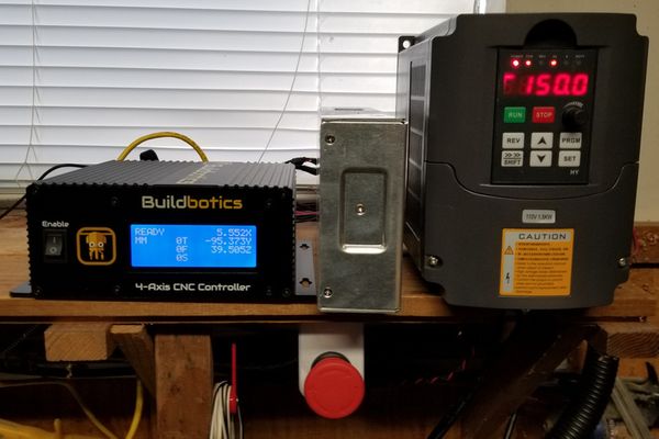
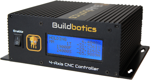
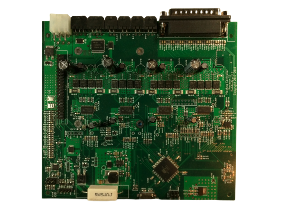
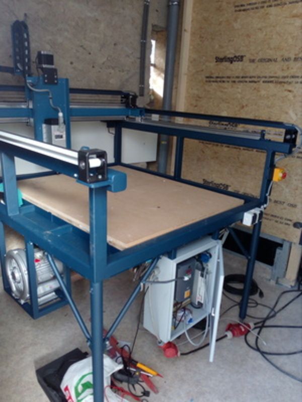
Inside the box, the Buildbotics CNC controller contains a Raspberry Pi 3 single board computer and four very powerful stepper motor drivers based on TI’s DRV8711 driver chip on a custom built PCB.
The step pulses are produced not by the RPi but by a dedicated ATxmega192a3u 8-bit system-on-a-chip from Microchip (formerly Atmel). Many people know this AVR microcontroller better from its use in Arduino boards.
Subscribe to the Buildbotics mailing list.
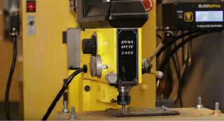
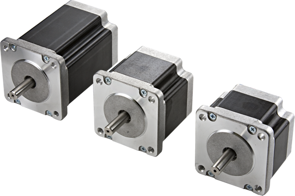
Stepper motor control
As the name suggests, stepper motors move in fixed steps. This allows them to be positioned with accuracy. Unlike DC motors, steppers have multiple coils which are activated in sequence to cause the motor to turn in the desired direction. Controlling them is more complicated than controlling plain DC motors so specialized driver chips are used.
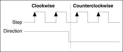
The stepper driver itself is controlled by a microcontroller which sends a stream of step pulses. The pulse rate determines motor velocity. It’s actually pretty easy to send high-speed pulses to the motor driver but in order to get smooth movement, the pulse stream must be tightly controlled. Velocity and acceleration must changed smoothly. Gaps in the pulse stream can cause motor stalls so the microcontroller must react very fast in order to make velocity changes with out interrupting the pulse stream.
8-bit Stepper Motor Drive
Up until recently, the common wisdom in the Maker community was that 8-bit AVR chips weren’t powerful enough to produce the high step rates needed to drive CNCs quickly and accurately, for many CNC controllers this is true. We initially started with a fork of the TinyG firmware because it already supported smooth S-curve acceleration not offered by other Open-Source CNC controllers. However, we found that the TinyG was barely able to keep up at high step rates and slight changes in the firmware could bring the whole thing tumbling down. The TinyG guys have since moved on to 32-bit ARM chips. Through a series of hacks, we were able to offload step production to the AVR’s hardware timers and DMA system. This frees up the AVR’s CPU for other tasks, such as path planning, and allows the Buildbotics controller to reach controlled step rates in excess of 250k/sec on four channels simultaneously without overtaxing the CPU.
Deep dive
Let’s dive a little deeper into the hacks we used to achieve these high step rates. The ATxmega192a3u contains seven 16-bit hardware timers; which is quite a few. The first change we made was to allocate a hardware timer to each stepper channel. Once configured, hardware timers operate independently of the CPU. The hardware timers can emit very high step rates at little cost but they must be reconfigured in order to change velocity and smooth S-curve acceleration requires continuous velocity changes.
In order to update the velocities, a fifth hardware timer was used. This timer interrupts the CPU every 5 milliseconds or 200 times a second. During these interrupts, each of the step clocks is stopped, reconfigured and restarted. Some extra care is taken to reduce clock jitter during these change overs.
These changes worked really well from the perspective of saving CPU time but there was no easy way to tell exactly how many steps each of the hardware clocks emitted during a 5ms period. Since the clock is deterministic, it is possible to compute exactly how many steps it will produce over a given time interval, in theory. In reality, it takes time for the CPU to stop, reconfigure and restart each of the clocks and this adds variance to the timing that is difficult to predict. The actual number of steps pulses produced could easily be one more or less than expected. Over time this would cause the CNC to drift away from its intended position with dire consequences.
The solution to this is to keep a count of the step pulses produced by the hardware clocks but how do you do this with out involving the CPU? If we had four more hardware clocks we could use them to count steps by linking two clocks together but, as I pointed out above, this chip has seven hardware clocks and we have already used five. The solution, hack the ATXmega’s DMA system.
DMA
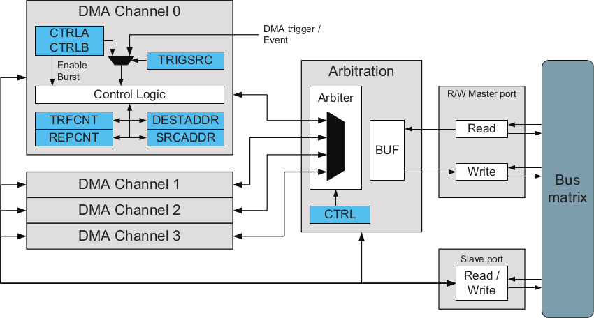
DMA stands for Direct Memory Access and is used to transfer data to or from memory and peripheral devices such as an I2C bus or serial port with out interrupting the CPU. I previously hacked other AVR peripherals to make them perform unintended functions and there were four DMA channels we weren’t using so it seemed like something might be possible. The trick was to figure out how to use the DMA channels as counters.
A failed attempt
My first idea was to use one of the DMA channel’s 24-bit source or destination address registers as the desired counters. The ATXmega’s hardware clocks have the capability of initiating a DMA transfer so we can trigger a DMA event on each step, just like we wanted. Unfortunately, on the ATXmega, this only works if the DMA transfer reads from one of the clock’s registers. Otherwise, the next DMA trigger will be ignored. So the DMA transfer must read from a clock register, which is at a fixed location and DMA transfer’s destination can be somewhere else in memory. Since we don’t want the DMA transfer stomping all over our RAM the write location has to be at a fixed address too. In our case, we just write to a fixed dummy variable. This only costs one byte of RAM for all four channels. But since both source and destination addresses must be fixed you cannot use the DMA address registers as counters of clock events.
Finally, success

This had me stumped for awhile but it seemed like there must be a way, so I kept digging in the ATxmega192a3u’s datasheet. Eventually, I figured out that it was possible to setup the DMA channel to do a fixed number of repeated transfers and, in the right mode, have each DMA event trigger one transfer and decrement the transfer counter until it reaches zero. Finally, this was the solution.
By setting the 16-bit transfer counter register to its maximum value of 65,535 we can let the clock run and each step output emits an event which triggers our dummy DMA transfer. The DMA transfer copies one byte of a timer register to our dummy variable and decrements the transfer counter. When, after 5ms, the step clocks are stopped and reconfigured, the change in the DMA transfer counter tells us exactly how many steps were output. As long as there are never more than 2¹⁶ steps over a 5ms period the transfer counter will never underrun but that would require over 13M steps/sec.
Conclusions
There are many other cool features to the Buildbotics CNC Controller and its companion software CAMotics that you can read about elsewhere. If you liked this article and are excited about what we are doing please tell other people and consider sharing on social media. All source code, schematics, PCB layouts and the enclosure design files can be found on our Github.