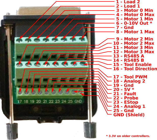
This is the pin-out diagram for the Buildbotics CNC Controller I/O breakout box shipped with most Buildbotics controllers. It has a DB25 connector which plugs in to the back of the Buildbotics controller and 26 screw terminals.
To connect a wire open the screw terminal by turning the screw counterclockwise with a small flat head screwdriver unit the gate is open. Strip about 1/4" (6mm) from the end of a 14-22 AWG wire and insert it into the open gate of the screw terminal. Then turn the screw clockwise to tighten. Do not over tighten as it will break the screw terminal.
Run all of the wires through the circular opening at the bottom of the box. Screw down the provided plastic strap to hold the wires in place. Double check all of your connections before closing the box and plugging it in to the 25-pin D-Sub connector on the back of the Buildbotics CNC controller. Turn the knurled plastic knobs clockwise to secure the breakout box to the controller.
Exceeding the voltage specifications of the Buildbotics controller can permanently damage it. If your controller says 24-48v on the back, the maximum voltage for all I/O connections is 5V. However, if you have an older controller that says 12-36v on the back it will be limited to 3.3V.
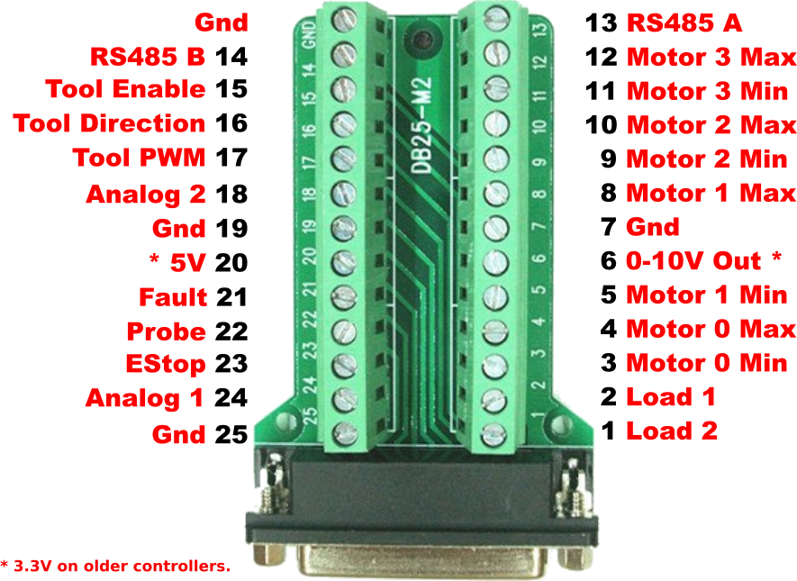
Above you will find the pin-out of the M2 I/O breakout board. Note that there is also an M version with a different pin-out. The screw terminals on this breakout board can be easier to access but it does not have a cover like the DB25 breakout box.
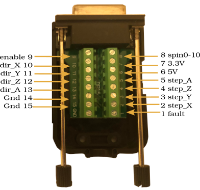
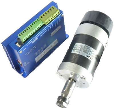
The DB15 breakout board provides access to the motor step and direction outputs which can be used to control external motor drivers. This makes it possible to use closed-loop steppers or server motors with the Buildbotics controller. The 0-10v output can be used to control analog spindles and can be a simpler alternative to using RS485 VFD control or PWM spindle control.