1. Introduction: Moving Beyond the "Slap a Bead on It" Advice
If you scroll through hobby CNC forums long enough looking for solutions to random mid-carve disconnects, computer dropouts, or mysterious emergency stop events, you will encounter a universal chorus of advice: “Slap some ferrite beads on your motor cables,” or “You need fully shielded cables.”
While adding beads and shielding can absolutely be valid fixes for a machine suffering from genuine electromagnetic interference (EMI), this advice is often handed out as a generic, reactive band-aid without any real diagnostic proof. If radio frequency (RF) energy or inductive cross-talk is actively causing false tripping on your machine, blindly stacking magnets on your wires won't tell you why it happened, where it's coming from, or how to truly prevent it.
I decided I didn’t want to just guess. I wanted to see the invisible electrical noise floating around my shop, track its behavior, and map exactly what it does to my machine.
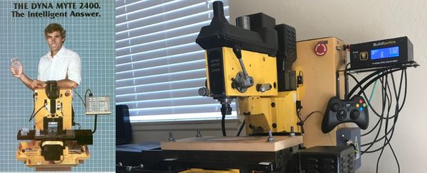
But here is the twist: I have run my CNC machine for several years with absolutely no ferrite beads or cable shielding, and it has never suffered from a single false trip or connection drop.
So why execute a rigorous, data-driven electromagnetic audit on a machine that already runs flawlessly?
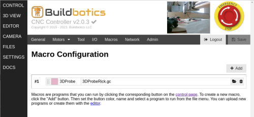
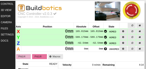
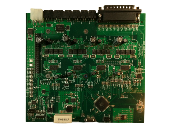
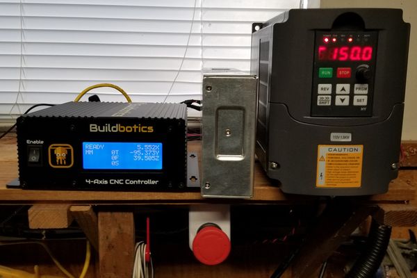
Because I wanted to understand the science behind that stability. My machine relies on a Buildbotics CNC Controller, a unit built with exceptional industrial hardware engineering. Many entry-level or budget control boards on the market are far less capable, featuring bare processor lines that collapse the second a nearby spindle kicks on.
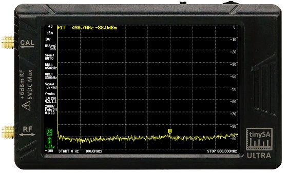
I deployed a tinySA Ultra spectrum analyzer running completely on its internal battery to sniff out airborne RF,
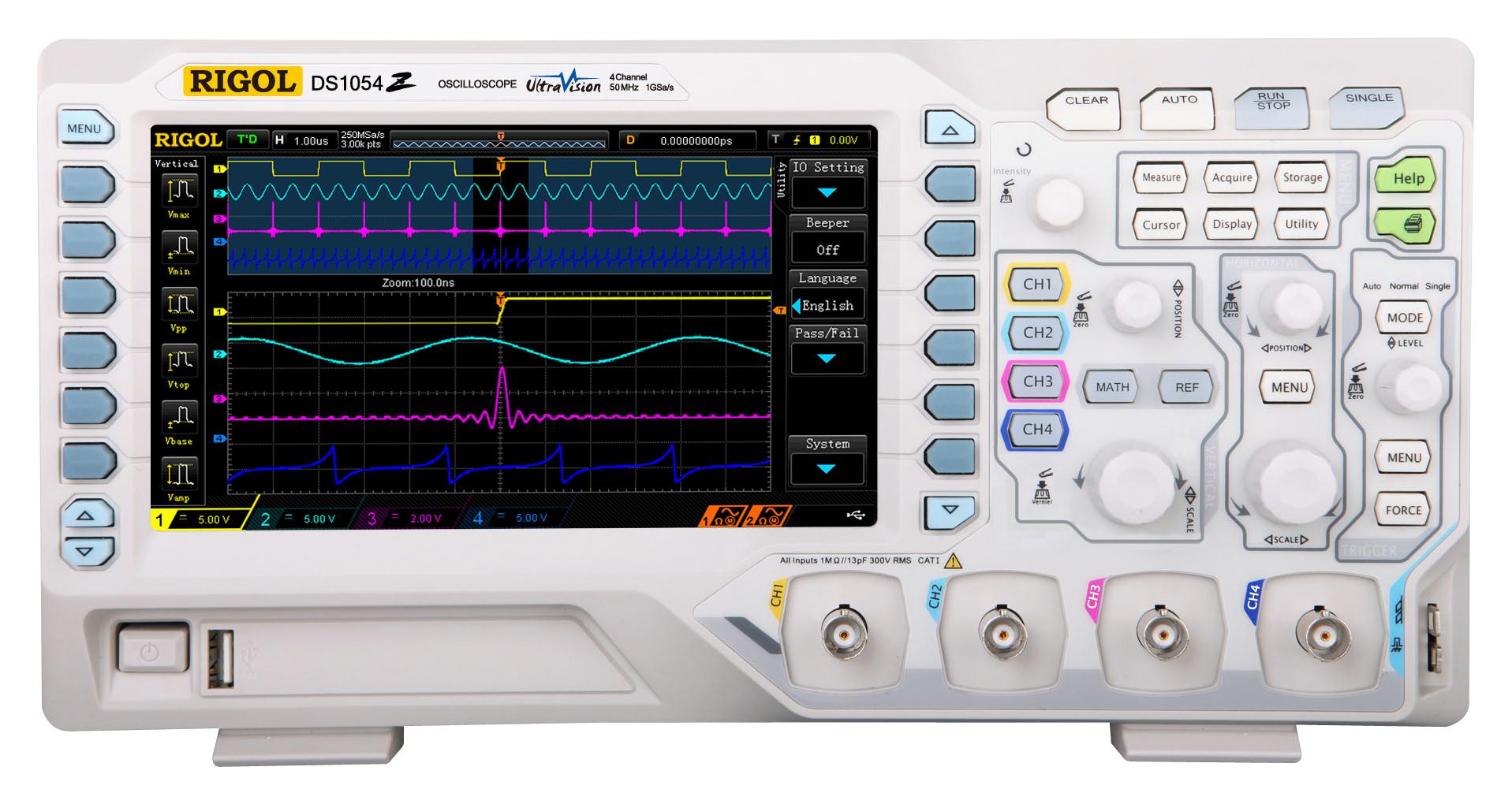
and a Rigol DS1054Z digital oscilloscope to measure the real-world voltage lines inside my controller,
This audit does two things: it exposes the brilliant engineering secrets that keep the Buildbotics platform immune to noise, and it provides a clear, proven diagnostic roadmap for hobbyists struggling to cure persistent EMI headaches on their own machines.
2. The Suspect Lineup: Where Does CNC Noise Come From?
To execute a proper electromagnetic audit, we first have to identify the potential rogue transmitters inside a typical CNC workspace. Any piece of active electronics operating in your shop can generate electromagnetic noise, but they fall into a few primary categories:
- The Power Supply Ecosystem: Many entry-level CNC setups rely on open-frame component power supplies that are only certified to lenient Class A (Industrial) limits, allowing raw RF noise to bleed freely from their ventilated metal mesh into an open room. To establish a clean, residential-ready standard for this audit, I upgraded the main supply feed to a MEAN WELL GST280A48-C6P desktop adapter. Because this fully sealed 48V brick is explicitly certified to strict FCC Part 15 Class B (Consumer/Residential) emission limits, it ensures that the raw power feeding our electronics is baseline quiet out of the gate.
- The CNC Controller: The internal microprocessor clocks, fast-switching FETs, and step-direction signal lines inside a mainboard are constantly humming with digital state changes.
- The Variable Frequency Drive (VFD): This is the ultimate heavy hitter. A VFD controls spindle speed by rapidly chopping high-voltage AC electricity down into aggressive pulse-width modulation (PWM) square waves, creating immense harmonic ringing.
- Computers and External Monitors: A shop laptop, its internal charging circuits, or a nearby desktop monitor can inject high-amplitude RF noise directly backward down data lines and power links.
- Peripherals & Accessories: USB cameras, digital gamepads, unshielded wireless dongles, and even cooling fans add their own microscopic noise profiles to the shared electrical ground.
The Real Enemy: Wires as Antennas
Here is a foundational truth of EMC engineering: While the active electronics listed above generate the high-frequency noise, the components themselves are usually too small to broadcast it very far into the room.
Instead, the noise rides out of the electronics housing and hitches a ride down your interconnecting cables.
Your 10-foot stepper motor lines and spindle power cords function exactly like perfectly tuned, long-wire transmitting antennas. When you pack these high-power cables tightly into the narrow plastic track of a drag chain right alongside low-voltage, highly sensitive digital limit switches or Z-probe wires, you create an ideal environment for inductive and capacitive cross-talk.
The high-power lines broadcast a localized blanket of electromagnetic energy, and the neighboring digital lines act as receiving antennas, catching the voltage ripples and feeding them directly back into the microprocessor. This is precisely why our near-field testing strategy focuses on sniffing the air directly inside the drag chain. We aren't just testing the components; we are testing the efficiency of the cables functioning as a rogue radio network right alongside our machine's nervous system.
3. The Physics of Interference: Near-Field vs. Far-Field Noise
To execute a meaningful electromagnetic audit, we must separate our measurements into two distinct physical zones. Electromagnetic energy behaves completely differently depending on how far it has traveled from its source wire. Understanding these two domains dictates exactly how we use our test equipment to isolate problems:
Near-Field Noise (The Self-Interference Zone)
The near-field is the region of space immediately surrounding your wires and electronics chassis—typically within one wavelength of the operating frequency. In this zone, energy does not travel through space as an organized, airborne electromagnetic wave. Instead, it exists as raw, localized magnetic (inductive) and electric (capacitive) field cross-talk.
- How we use it: If your CNC machine is experiencing physical stability problems—such as random mid-carve emergency stops or computer disconnects—near-field measurements are the only ones that matter. By taping our 1-foot whip antenna directly to the drag chain, we are intentionally sampling this chaotic cross-talk environment. This test tracks the exact energy profile that is trying to leap across the wire insulation from your high-power motor lines straight into your sensitive digital inputs.
Far-Field Noise (The Regulatory Compliance Zone)
As electromagnetic energy moves further away from the machine, the electric and magnetic fields couple together permanently. They form a true plane wave that breaks away from the wiring completely, radiating out into the open room and traveling through walls. This is the zone where federal regulators care about your shop.
- How we use it: To check for legal FCC compliance, we move our spectrum analyzer 10 feet (3 meters) away from the machine. At this distance, the localized drag-chain cross-talk disappears from the airwaves, leaving only the pure radiated signals that have successfully escaped the machine's wiring network. This test tells us whether our shop is actively broadcasting illegal radio interference that could disrupt a neighbor's Wi-Fi, television, or cellular reception.
The Regulatory Catch-22: Who is Responsible?
It is a common misconception that every individual component you buy for a hobby CNC project must carry an FCC compliance sticker. Under FCC Part 15 regulations, standalone sub-assemblies—such as bare stepper motors, developer microcontrollers, and control modules like the Buildbotics Controller—are generally exempt from independent certification because they cannot function on their own out of the box.
However, the regulations feature a massive catch: the final system integrator—which means you, the person wiring all these parts together onto a structural frame—is legally responsible for the compliance of the total machine.
4. Raw Near-Field Auditing & The Voltage Reality
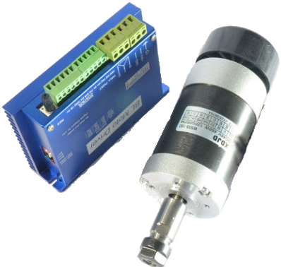
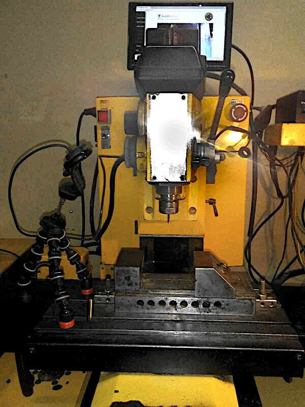
To get an accurate measure of the noise that the digital inputs experience, I taped the tinySA directly to the drag chain carrying the power cable from the Huanyang VFD, the motor cables connected to the X and Z axis motors, and the input signals for the X and Z axis limit switches.
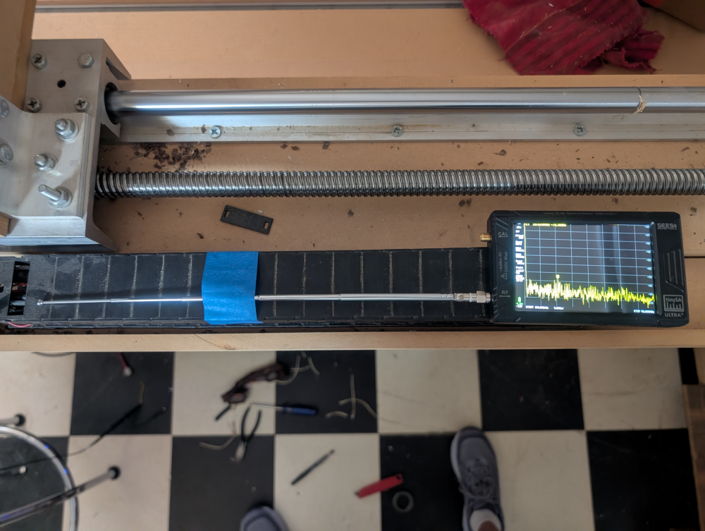
Recall that these initial tests were done with the machine set up as it has been running for years, that is, with no beads on the motor cables and no toroid protecting VFD power cable.
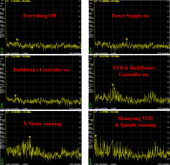
By sweeping a window from 100 kHz to 40 MHz, I captured a detailed six-part chronological map of the electromagnetic noise inside the chain as each component powered up. Running the tinySA purely on battery power completely isolated the test environment, exposing the raw, unpolluted truth:
Decoding the Six-Pane Scan Matrix
- 1. Everything Off (-88.0 dBm @ 6.41 MHz): This is our baseline environmental control scan with the entire shop powered down. The spectrum is beautifully flat and sitting deep in the static floor at -88 dBm, proving that there is no external ambient RF contamination leaking into our drag chain from the outside world.
- 2. Power Supply On (-87.0 dBm @ 17.40 MHz): Next, I flipped on our new MEAN WELL GST280A48-C6P desktop power brick. The spectrum barely budged, showing a tiny blip at 17.4 MHz but keeping the rest of the noise floor completely flat. This confirms that this Class B certified residential supply successfully traps its internal switching oscillation inside its sealed housing.
- 3. Buildbotics Controller On (-90 dBm @ 5.41 MHz): Turning on the Buildbotics Controller did not introduce any discernable noise.
- 4. VFD & Buildbotics Controller On (-68 dBm at 5 MHz and -75dBm at 30MHz): Flipping the power switch on the Huanyang VFD introduces our very first sign of real electromagnetic activity. Even with the spindle at a dead stop, a jagged, broadband "noise mountain" begins swelling upward between 5 MHz and 15 MHz and between 25 MHz and 35MHz. Because this budget VFD uses a plastic enclosure rather than a cast-metal grounded chassis, its internal idling power electronics actively radiate RF energy straight through the plastic housing and into the adjacent antenna.
- 5. X Motor Running (-60 dBm @ 13 MHz): The moment the X-axis motor begins stepping back and forth, a prominent harmonic spike punches through the noise floor, jumping up by about 30 dB to hit -60 dBm near 13 MHz. This represents the fast pulse-width modulation (PWM) chopping frequency of the internal Texas Instruments stepper drivers radiating straight off the unshielded 10-foot motor lines.
- 6. Huanyang VFD & Spindle Running (-60 dBm @ 110KHz): The instant the VFD fires up and spins the spindle motor, a violent, high-amplitude energy surge floods the lower end of our spectrum, peaking at -60 dBm down at 0.11 MHz.
On a spectrum analyzer screen, an airborne spike climbing all the way to -60 dBm inside your drag chain looks incredibly intimidating. This is exactly the kind of graph that causes hobbyists to panic and assume their machine is on the verge of a catastrophic crash. But what does that airborne radio signal actually do to a physical copper wire sitting right next to it?
Hooking Up the Oscilloscope: Volts vs. Logic Thresholds
To move past radio frequency theory and measure the actual electrical impact on our physical wire lines, I fired up my Rigol DS1054Z digital oscilloscope. I placed a probe directly across the input signal pin and ground of an active limit switch right at the terminal block of the Buildbotics Controller.
If the airborne radio waves captured by the tinySA were truly threatening our machine's stability, we would see violent voltage transients completely overwhelming our digital circuit. Instead, the scope traces revealed a masterclass in real-world circuit behavior.
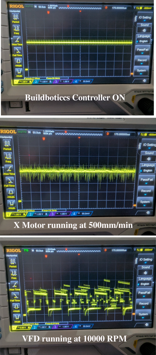
- Top Pane: Buildbotics Controller ON (Baseline): With the controller fully powered up but all motors idle, the 3.3V DC digital input line is an absolute straight line. The signal is incredibly clean, showing a completely stable digital "HIGH" state with no stray voltage fluctuations or ripples present at 1.00 Volt per division.
- Center Pane: X Motor Running at 500mm/min: When the stepper motor is activated, the unshielded wires begin transmitting the high-frequency PWM switching profile of the stepper drivers. Because our long limit switch wires are unshielded, they behave like an open antenna, capacitively picking up that energy. At 1.00 Volt per division, this noise band actively measures a substantial 1.5 Volts peak-to-peak, swinging the line up toward 4.0V and pulling it down to roughly 2.5V.
- Bottom Pane: VFD Running at 10,000 RPM: The final trace captures a staggering electrical reality when the spindle is actively spinning. Because the VFD uses high-voltage, high-power switching pulses, the capacitive coupling inside the drag chain scales up exponentially. Look closely at the vertical scale on the left edge of the screen: the scope has stepped up from 1V/div to 5.00 Volts per division. At this scale, the periodic switching spikes and voltage settling waves are ringing across more than a full grid square, revealing an induced noise profile measuring a massive noise voltage ranging from +15V to -1V!.
The Real Reason the Machine Doesn't Trip
Seeing a 1.5V noise band from the steppers—and a massive 16V ringing waveform from the spindle—riding on top of a 3.3V logic circuit would make any textbook engineer predict an instant system crash. In normal circumstances, a 15V spike would effortlessly overdrive the microprocessor input entirely via overvoltage and the negative swings would certainly trip the input limit switch. Yet, my machine has run flawlessly for years without a single false trip.
How is this possible?
First, we have to look at the ATxmega processor's input thresholds. To register a digital logic change from a HIGH state to an active LOW state (triggering an E-stop), the voltage must drop below ~0.9 Volts. On the stepper motor trace, our 1.5V peak-to-peak swing only pulls the line down to about 2.5 Volts, meaning the signal safely floats well above the danger zone.
But what about that massive 15V spindle transient? Left unmanaged, that spike would pull the input into negative volts and blast it past +15V, possibly destroying the chip. It doesn't crash because of the exceptional hardware protection built directly into the Buildbotics CNC Controller.
The digital inputs on the Buildbotics mainboard feature ultra-fast Schottky protection diodes pointing outward with a 100V reverse breakdown. The instant the unshielded spindle line induces a high-voltage spike inside the drag chain, these diodes become reverse biased and block the high voltage before it can cross into the microprocessor.
The spikes that go below the .9V threshold are neutralized by the controller's programmable software debounce timing. Because RF noise oscillates rapidly millions of times per second, the firmware demands that an input signal remain continuously and solidly held down for a steady 5 millisecond window before recognizing it as a real switch closure. The massive 15V spike is chopped down by the hardware and ignored by the software, proving that intelligent circuit design will easily defeat brutal near-field noise environments.
5. Taming the Near-Field: Do Ferrites Actually Work?
Even though our raw baseline testing proved that the Buildbotics Controller remains perfectly stable under fire, leaving large voltage swings bouncing around input lines goes against standard shop advice. To see if the common internet remedies actually hold weight, I re-installed our two hardware countermeasures: a linear stack of five clip-on ferrite beads on the stepper motor wires, and a heavy toroid choke core on the main VFD output lines feeding the spindle.
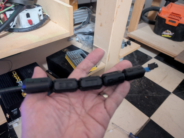
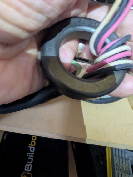
The side-by-side oscilloscope captures revealed a fascinating disconnect between internet forum lore and real bench physics:
The Stepper Motor: A Noticeable Win for the Beads
When we check the scope traces for the running X-axis stepper motor (1.00 Volt per division), the five clip-on ferrites deliver a clear, measurable improvement:
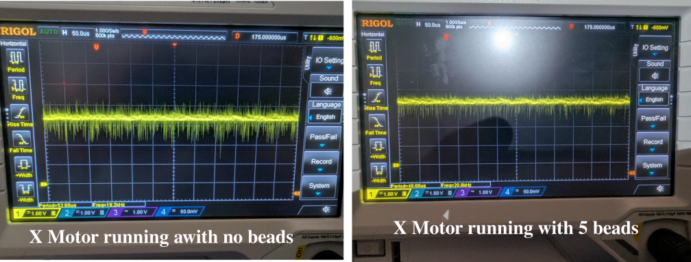
- Left Pane (No Beads): The raw PWM motor-chopping frequency couples into our unshielded limit switch line, creating a thick, fuzzy band of noise measuring a substantial 1.5 Volts peak-to-peak around our 3.3V rail.
- Right Pane (With 5 Beads): The moment the five ferrite beads are snapped over the line, they act as a high-frequency choke. On the scope, the thick, fuzzy voltage envelope noticeably compresses. While it doesn't flatten the signal completely, it takes a clean bite out of the peak-to-peak ripple, visibly thinning out the fuzzy noise band.
The VFD Spindle: The Toroid Myth Exploded
The story completely changes when we look at the high-power spindle lines running at full 10,000 RPM. When we look at the scope traces at 5.00 Volts per division, we see a reality check that goes entirely against common blog advice:
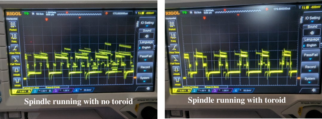
- Left Pane (No Toroid): The raw, unshielded VFD lines induce a heavy, erratic ringing pattern onto our limit switch line that surges across the screen, reaching 15 Volts peak-to-peak.
- Right Pane (With Toroid): After wrapping the heavy UVW spindle lines through the magnetic toroid core, the result on the scope is a bit of a letdown. The toroid has almost no noticeable effect on the voltage swing. The chaotic spikes and multi-volt surges remain practically identical to the unshielded run, showing only a microscopic reduction in peak height.
Simply wrapping your spindle lines through a toroid does practically nothing to solve near-field cross-talk inside a drag chain. The raw current and capacitive coupling running parallel over 10 feet completely overwhelms what a single magnetic ring can filter out at these lower frequencies.
The Buildbotics Advantage: Silicon over Ferrites
This test exposes exactly why so many hobbyists get stuck in an endless loop of buying filters. If you are running an entry-level controller with bare microprocessor pins, relying on a VFD toroid to fix your false trips is a losing battle—the noise is still hitting your board at full strength.
The only reason my machine has carved flawlessly for years without a single false trip comes down entirely to the internal architecture of the Buildbotics CNC Controller:
These tests demonstrate that traditional, forum-vouched hardware fixes like clip-on ferrite beads and magnetic toroid chokes offer mixed results against intense near-field electromagnetic noise. While five snap-on ferrite beads provide a clear, measurable reduction in peak-to-peak ripple on unshielded stepper motor lines, a heavy magnetic toroid core wrapped around VFD spindle power lines fails to produce any noticeable impact on massive 15V-to-1V ringing transients. Ultimately, the test reveals that external filters cannot match the protection of robust, onboard hardware architecture—proving that the Buildbotics Controller’s internal Schottky protection diodes and programmable software debouncing are what truly shield sensitive microprocessor logic circuits from catastrophic cross-talk and false limit-switch trips.
6. Turning to the Airwaves: The Far-Field Subtraction Protocol
With our near-field drag chain environment thoroughly understood, it was time to step back 10 feet (3 meters) and analyze our integrated machine from a regulatory standpoint across the official FCC radiated emissions spectrum: 30 MHz to 1000 MHz (1 GHz).
However, open-air EMI testing outside of a million-dollar shielded anechoic chamber presents a massive challenge: the airwaves are already flooded with external radio signals. While it is not possible to do testing comparable to an FCC certified test lab in my garage, the tinySA has a great feature that attempts to subtract background noise. (Quite impressive for a device that you can get on Amazon for less than $100. Oh, and I should mention that its an open source project!)
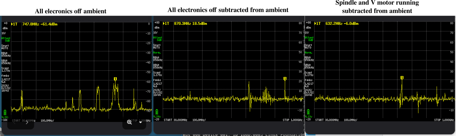
The graph on the left is the noise spectrum with my CNC machine completely turned off. As you can see there multiple spikes of massive amounts of RF signal across this spectrum. A live view reveals that these signals are constantly changing, especially around 630, 750, and 880MHz. These are all cell phone bands and cannot be completely subtracted by the tinySA because they are constantly changing with network traffic.
Even still, the middle graph shows the RF signals present with the CNC machine completely off minus the baseline on the left. While the first graph measures the actual signal power in dBm, the middle and right graphs show the deviation from the baseline in dB. Since the cell traffic is constantly changing the subtraction still shows significant RF signal around those frequencies.
The graph on the right shows the RF signal captured with the CNC machine on and the X motor running at 500mm/minute and the spindle running at 10000 RPM.
This test suggests that my CNC Machine which is powered by the Mean Well GST280A48-C6P power adapter, the Buildbotics Controller, and the Huanyang VFD would easily pass an FCC certification.